
Inhalation anaesthesia delivery system and method

a delivery system and anaesthesia technology, applied in the field of inhalation anaesthesia delivery systems, can solve the problems of affecting the quality of inhalation anaesthesia, so as to achieve reliable results, save anaesthesia, and be easily measurable

Active Publication Date: 2014-07-22
GENERAL ELECTRIC CO
View PDF12 Cites 7 Cited by
  • Summary
  • Abstract
  • Description
  • Claims
  • Application Information

AI Technical Summary

Benefits of technology

The invention relates to a system for controlled delivery of oxygen in a breathing circuit. The system uses an oxygen sensor to measure the concentration of oxygen in the breathed air, and adjusts the composition of the oxygen delivery to match the target value. The control system is backed up with a separate measure of oxygen in the body, which ensures safe delivery. The system allows for control over the speed and gas composition of the oxygen delivery, and can be used with various volatile anesthetic agents. The system is easy to use and produces reliable results, making it a useful tool in medical settings.

Problems solved by technology

Difficulty to control the oxygen reservoirs arises in low fresh gas flows where the system time constant for the control may be measured in tens of minutes.
However, EtO2 suffers of the problem that some lung ventilation / blood perfusion mismatch conditions may disturb the connection between the measured EtO2 and body oxygen storage status.
As a result of such disturbances, EtO2 measurement may overestimate the filling grade of the body oxygen reservoirs.
Disadvantage of the inspired gas control is vague correlation with patient oxygenation state, specially during instable situations where the patient O2 level is changed.
Controlling SpO2 involves a problem of poor sensitivity when patient oxygenation is normal, i.e. SpO2 is above 95%.

Method used


Image

  • Inhalation anaesthesia delivery system and method
  • Inhalation anaesthesia delivery system and method
  • Inhalation anaesthesia delivery system and method

Examples


Embodiment Construction

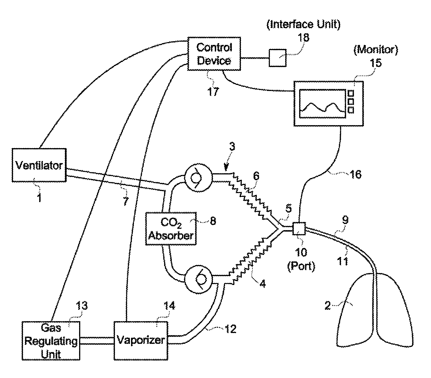
[0017]FIG. 1 shows the anaesthesia environment the method may be applied in connection with the invention. Ventilator 1 fills patient lungs 2 during inspiration by pressurizing the breathing circuit 3. Breathing circuit comprises of inspiration limb 4, Y-piece 5, expiration limb 6, ventilator limb 7, CO2 absorber 8, and patient limb 9. Inspiration and expiration limbs include unidirectional valve to direct the inspiration and expiration gas flow to respective limbs. Patient limb includes gas monitor sampling port 10 and intubation tube 11 connecting the patient with the breathing circuit. In operation, ventilator receives the expired gas from the patient during expiration and stores the gas for the next inspiration. At inspiration the gas is guided through CO2 absorber, where the CO2 is removed, to inspiration limb and further to patient lungs. Breathing gas is brought into the breathing circuit from fresh gas line 12. The breathing gas is a mixture of O2, N2O or N2 (air) from gas r...


PUM


Abstract

An inhalation anesthesia delivery system and method, wherein the system includes a fresh gas feeding arrangement connected to a breathing circuit, a monitor device, a control device and an interface unit. The fresh gas feeding arrangement is configured to deliver a desired concentration of gas to the breathing circuit, the desired concentration being set by using the interface unit. The monitor device is configured to monitor gas concentrations in the breathing circuit by analyzing gases flowing in the breathing circuit, and the control device is configured to control the fresh gas feeding arrangement on the basis of the data received from the monitor device to keep the desired breathing gas concentration. The control device is also configured to monitor expired inorganic gas concentration by comparing the measured expired breathing gas concentration with the set target value and changing the fresh gas delivery accordingly to meet the target value.

Description

BACKGROUND[0001]1. Field of the Invention[0002]The field of the invention relates to an inhalation anaesthesia delivery systems generally, and more particularly to an inhalation anaesthesia delivery system comprising a fresh gas feeding arrangement connected to a breathing circuit, a monitor device, a control device and an interface unit, whereby the fresh gas feeding arrangement and the ventilator are configured to deliver a desired concentration of gas to the breathing circuit, and to a method of operating the same.[0003]2. Description of Prior Art[0004]The inhalation anaesthesia delivery systems are used to maintain oxygen (O2) and carbon dioxide (CO2) exchange of the patient during anaesthesia. During inspiration oxygen enriched gas flows into the lungs where it is diffused into circulation. At the same time CO2 is diffusing from the circulation into the lungs. During expiration the oxygen depleted and CO2 enriched gas flows out from the lungs. Inspiration and expiration togethe...

Claims


Application Information

Patent Timeline
Patent Type & Authority Patents(United States)
IPC IPC(8): A61M15/00A61B5/08A61M16/00
CPCA61M16/01A61M16/0875A61M16/104A61M16/18A61M16/22A61M2202/0208A61M2202/0241A61M2202/0283A61M2202/0291A61M2230/435A61M2230/437A61M16/085
Inventor HEINONEN, ERKKI PAAVOHAGGBLOM, TOM JAKHALINEN, HENRIIKKA
Owner GENERAL ELECTRIC CO
Learn More