
Component-based lighting

Inactive Publication Date: 2014-07-08
PIXAR ANIMATION
View PDF0 Cites 39 Cited by
  • Summary
  • Abstract
  • Description
  • Claims
  • Application Information

AI Technical Summary

Benefits of technology

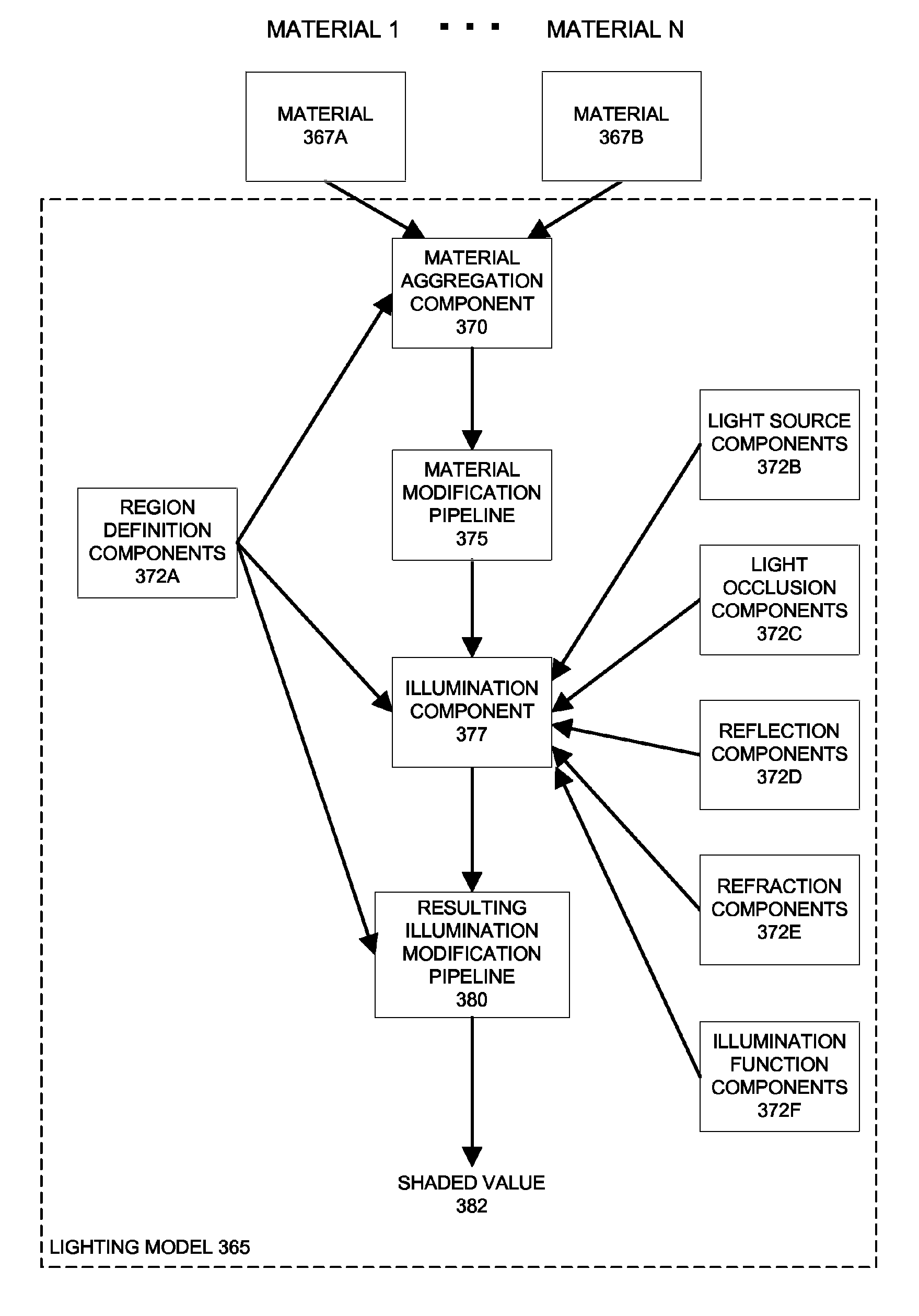
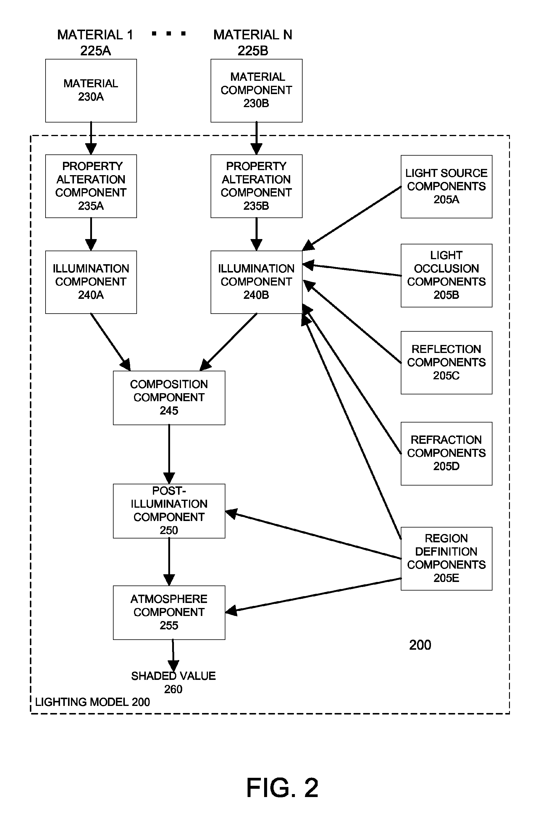
The invention uses component-based rendering and lightning models to generate realistic and efficient images. The components are dynamic and can output or receive data of any type and quantity without needing advanced knowledge of the other components. The components can be bound together, allowing for seamless dataflow without compiling or recompiling them. They can represent any function or operation associated with rendering, including materials, light sources, color, compositing functions, and post-illumination effects. The invention allows for efficient and effective rendering of complex scenes with millions of assets and fine-grained effects.

Problems solved by technology

One problem with this approach is that shader programs are typically tied to a surface or object in a scene.
This limits artistic reflection, as most changes to the illumination must be made by modifying the shader programs of the object.
Moreover, lights broadcast values to shaders associated with objects, but material shaders cannot communicate with lights.
Thus, illumination computations are limited to effects in which light parameters are received and the material shader program then respond to these parameters.
There is no way to perform illumination computations that modify light parameters in response to material shader programs.
This process is time-consuming, unwieldy, and error prone.
Moreover, many parameters of a light may contradict each other if used incorrectly.
These parameters, if used incorrectly, could interact in unpredictable ways.
These routines add substantial overhead, decreasing rendering performance.

Method used


Image

  • Component-based lighting
  • Component-based lighting
  • Component-based lighting

Examples


Embodiment Construction

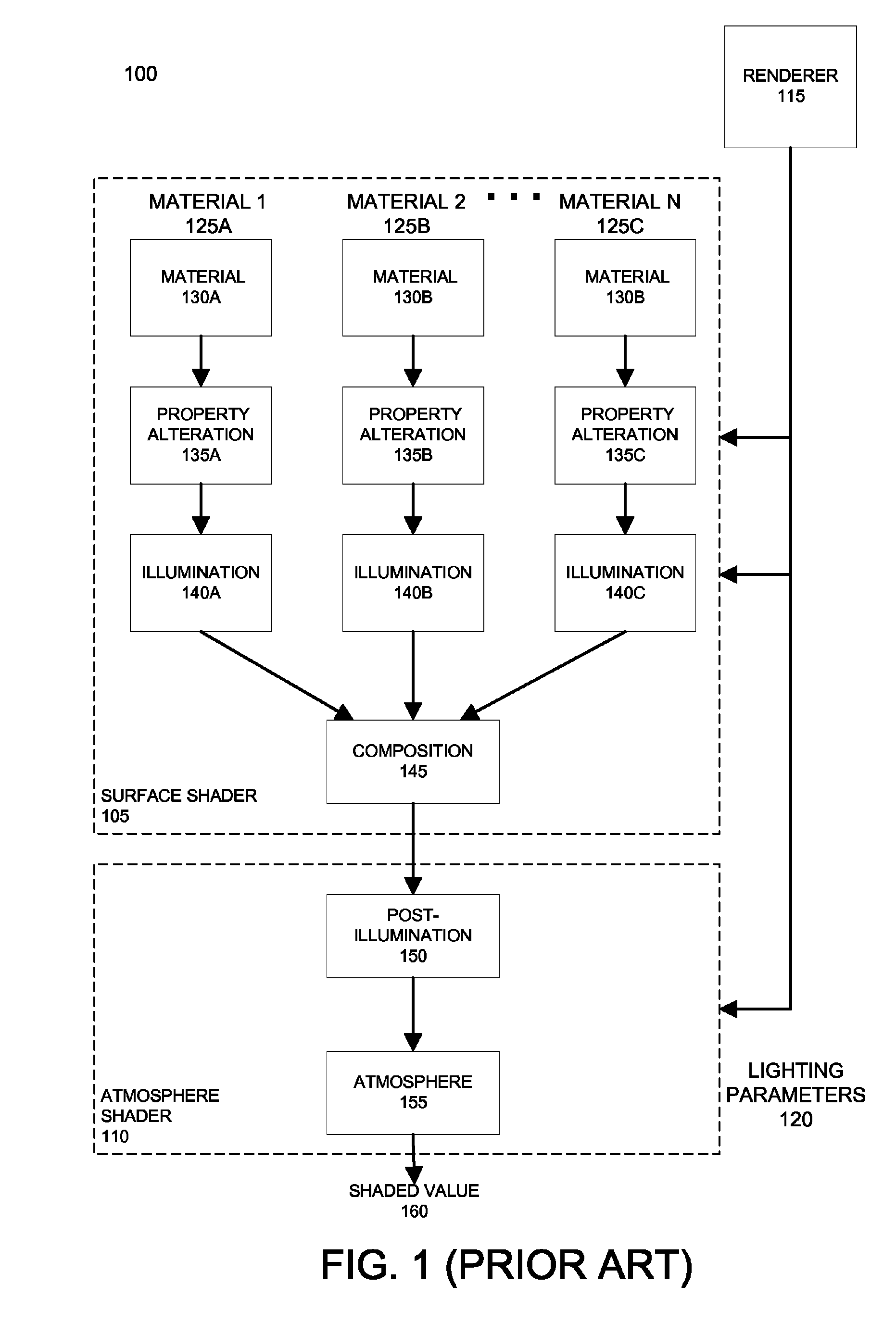
[0022]FIG. 1 illustrates a prior architecture 100 for representing lights in computer graphics systems. Architecture 100 includes two monolithic shader programs, a surface shader program 105 and an atmosphere shader program 110. A renderer 115 executes shader programs 105 and 110 at least once for each portion of scene geometry, such as a micropolygon or polygon fragment, that potentially contributes to the value of a pixel or sub-pixel sample in a rendered image.

[0023]The surface shader program 105 determines the shading from the interaction of one or more lights with the portion of scene geometry. In one implementation, surface shader program 105 handles the shading of one or more lights potentially illuminating a portion of scene geometry, such as a particle, a micropolygon, or a polygon fragment associated with a surface or a volume. The properties, such as the color, opacity, displacement, or normal vector, of each portion of scene geometry can be defined, at least in part, by ...


PUM


Abstract

Component-based rendering and lightning models process scene data to generate rendered images. Components include input and output parameters, data, and / or instructions for evaluation. The component parameters are dynamically typed, so that each component can output data of any arbitrary type and / or quantity to receiving components. The components can also receive data of any type and / or quantity without any advance knowledge of the existence or functionality of the sending component or its output's data type. The components are dynamically bound, so that the dataflow between components is expressed without recompiling components or scene data. Components can be classified into categories, typically representing a discrete functions, operations, or related properties. Components can represent any function or operation associated with rendering, including materials, light sources; colorer components; region definition components; occlusion components; property alteration components; illumination components; reflection and refraction components; broadcasting components; compositing components; post-illumination components; and general utility or modification components.

Description

CROSS-REFERENCE TO RELATED APPLICATIONS[0001]This application claims priority to U.S. Provisional Patent Application No. 60 / 791,630, filed Apr. 12, 2006, and entitled “Component-Based Lighting,” which is incorporated by reference herein for all purposes.BACKGROUND OF THE INVENTION[0002]The present invention relates to the field of computer graphics, and in particular to methods and apparatus for creating, modifying, and using lights and other components to control the attributes and appearance of objects in computer graphics images. Many computer graphic images are created by mathematically modeling the interaction of light with a three dimensional scene from a given viewpoint. This process, called rendering, generates a two-dimensional image of the scene from the given viewpoint, and is analogous to taking a photograph of a real-world scene. Animated sequences can be created by rendering a sequence of images of a scene as the scene is gradually changed over time. A great deal of ef...

Claims


Application Information

Patent Timeline
IPC IPC(8): G06T17/00G06T15/60G06T15/50
CPCG06T15/60G06T17/00G06T15/50G06T15/506
Inventor SMYRL, ELIOT
Owner PIXAR ANIMATION
Learn More