Horizontal machining center

a horizontal machining and center technology, applied in the direction of manufacturing tools, metal-working machine components, transportation and packaging, etc., can solve the problem of having a bulky structure in the horizontal machining center, and achieve the effect of preventing a bulky structure and simple structur

Inactive Publication Date: 2014-07-08
DMG MORI CO LTD
View PDF9 Cites 0 Cited by
  • Summary
  • Abstract
  • Description
  • Claims
  • Application Information

AI Technical Summary

Benefits of technology

[0008]The present invention has been made to overcome the above disadvantage and it contemplates a horizontal machining center having a simple structure and prevented from having a bulky structure.
[0010]The horizontal machining center thus configured allows tools to be exchanged while the coupling mechanism operates to gang the magazine and the table together in moving them. This can eliminate the necessity of introducing an additional driving source for sliding the magazine in the direction parallel to the predetermined axis, and the horizontal machining center can have a simple structure. In doing so, as the table is driven in a direction, the magazine is moved in an opposite direction, and moving the magazine away from the spindle, or in the second direction, to remove a tool attached to the spindle from the spindle can be done simply by moving the table to approach the spindle, or in the first direction. It is no longer necessary to drive the table for an increased distance for exchanging tools, and the horizontal machining center can thus be prevented from having a bulky structure.
[0012]In the horizontal machining center thus configured, the chain supporting mechanism disposed in the vicinity of the tool exchange position of the spindle can support the chain to have a portion disposed more adjacent to the spindle. This allows tools to be exchanged in a reduced period of time.
[0014]The horizontal machining center thus configured can have the magazine attached via the guiding mechanism to the bed directly and hence disposed more adjacent to the spindle. This allows tools to be exchanged in a reduced period of time. Furthermore, a reduced number of components can also be achieved.
[0015]The present invention can thus provide a horizontal machining center having a simple structure and prevented from having a bulky structure.

Problems solved by technology

In doing so, if the table is moved away from the spindle to be farther than the origin of the Z-axis, the table's Z-axis travel must be set to be longer than original, resulting in the horizontal machining center having a bulky structure.

Method used


Image

  • Horizontal machining center
  • Horizontal machining center
  • Horizontal machining center

Examples


Embodiment Construction

[0027]Hereinafter the present invention in embodiment will be described with reference to the drawings. In the figures, identical or corresponding components are identically denoted.

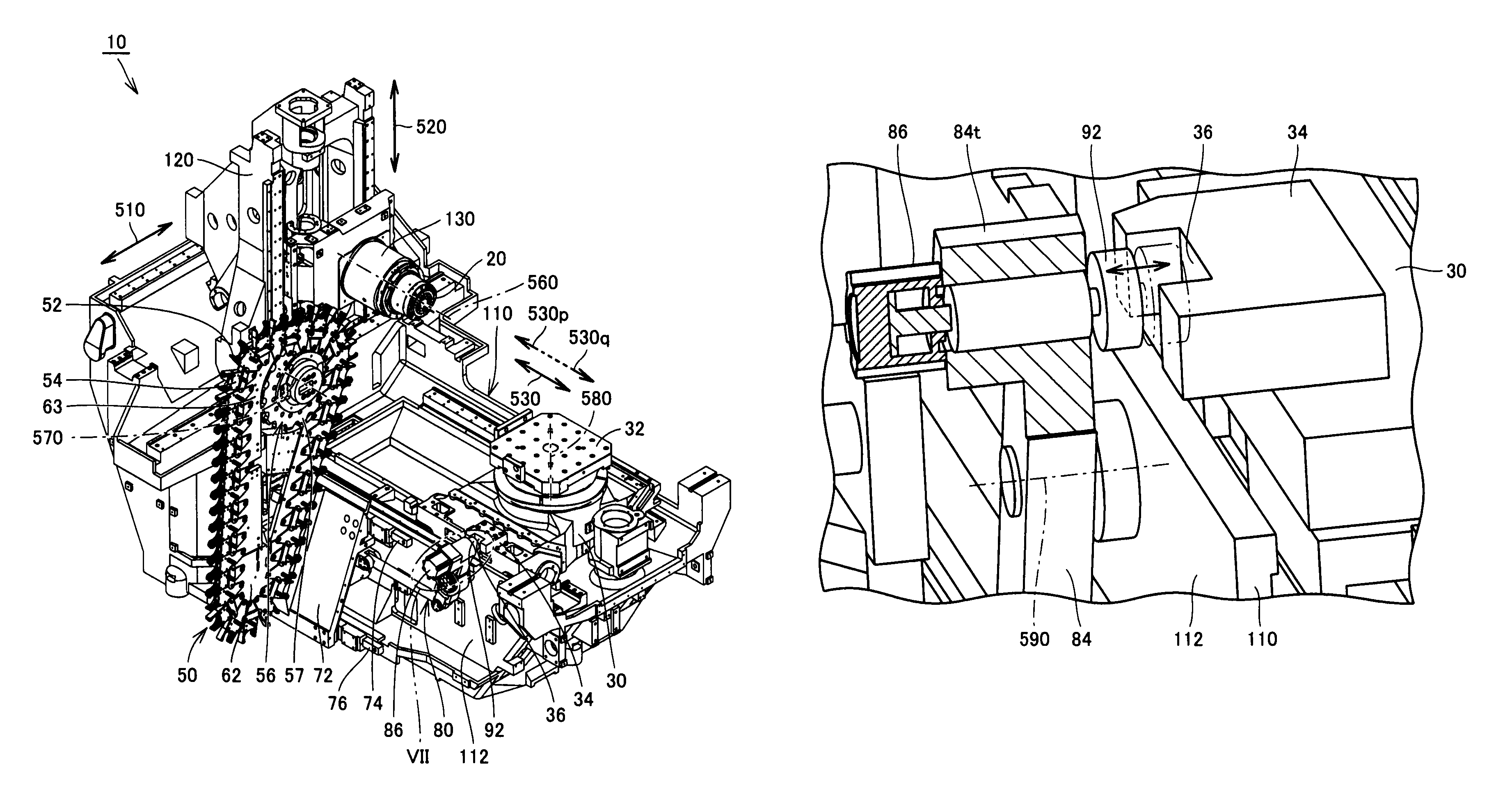
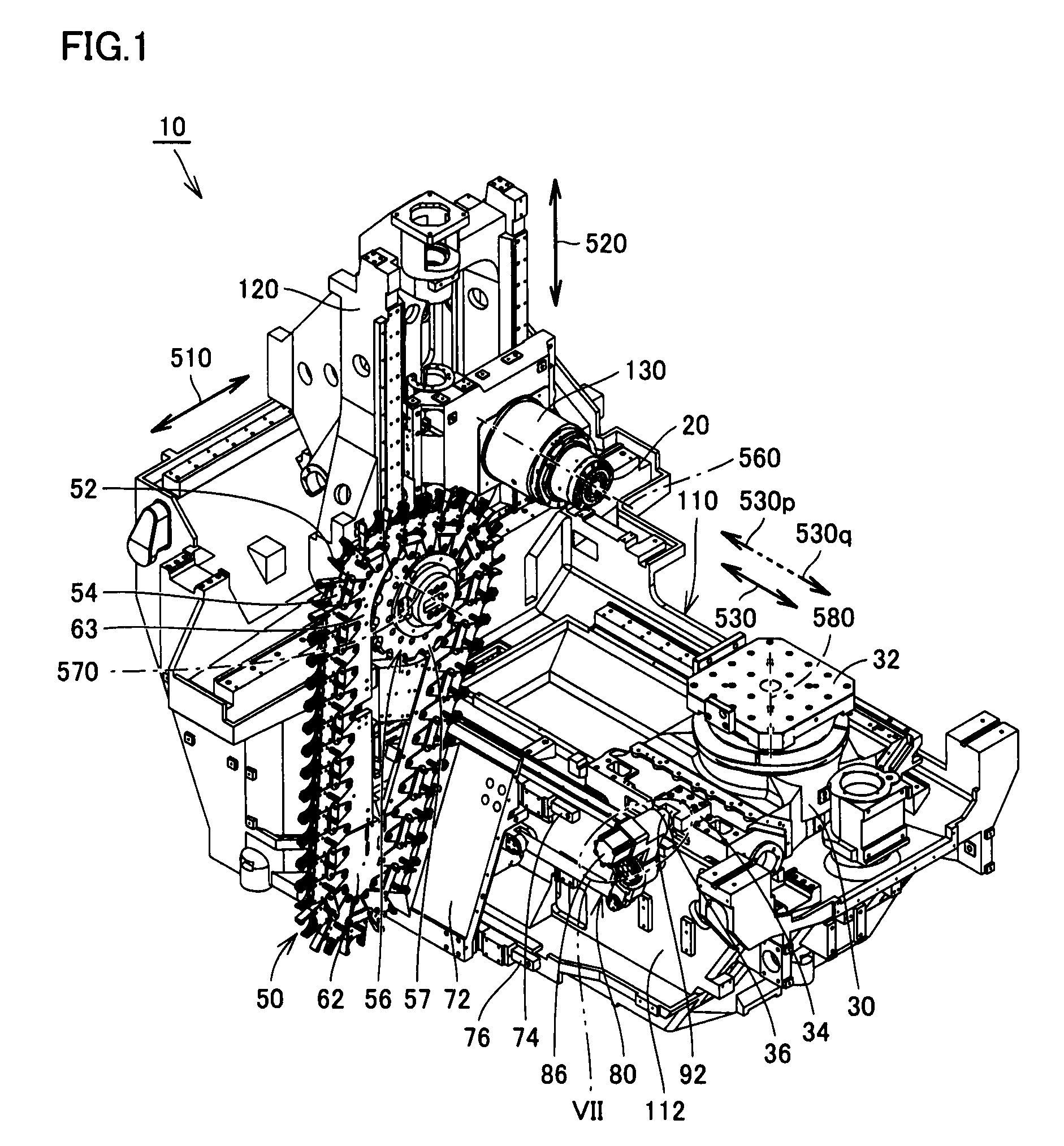
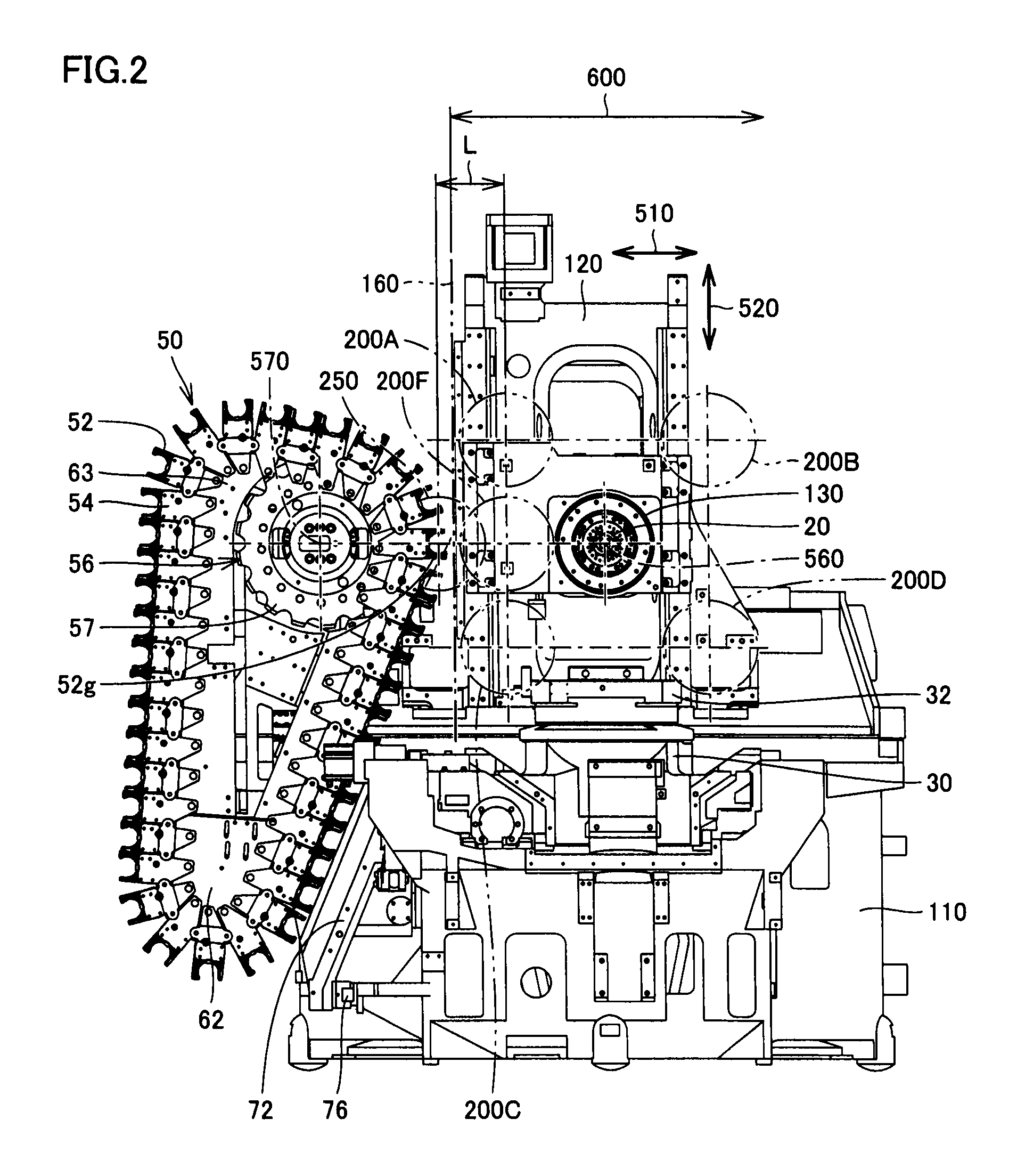
[0028]FIG. 1 is a perspective view of a horizontal machining center in an embodiment of the present invention. FIG. 2 is a front view of the FIG. 1 horizontal machining center. FIG. 3 is a side view of the FIG. 1 horizontal machining center. FIG. 4 is a plan view of the FIG. 1 horizontal machining center.

[0029]With reference to FIGS. 1-4, the present embodiment provides a horizontal machining center 10 having a basic structure, as will be described hereinafter. Horizontal machining center 10 has as its main components a bed 110, a column 120, a spindle head 130, and a table 30.

[0030]Bed 110 is a base member for mounting column 120, spindle head 130, table 30 and the like thereon, and set on an installation plane in a factory or the like. Bed 110 has column 120 attached thereto. Column 120 is provided on ...


PUM


Abstract

A horizontal machining center includes: a table driven in first and second directions (directions indicated by arrows 530p and 530q, respectively) allowing the table to approach and move away from a spindle, respectively; a magazine having a plurality of tool gripping claws; and a coupling mechanism for coupling the table and the magazine together and moving the magazine in one of the first and second directions when the table is driven in the other of the first and second directions. When a tool attached to the spindle is removed from the spindle, the table is driven in the first direction, and when a tool accommodated by the magazine is attached to the spindle, the table is driven in the second direction. A horizontal machining center having a simple structure and prevented from having a bulky structure can thus be accomplished.

Description

BACKGROUND OF THE INVENTION[0001]1. Field of the Invention[0002]The present invention relates generally to a horizontal machining center, and particularly to a horizontal machining center having a column, a spindle head and a table sliding in X-, Y- and Z-axes, respectively.[0003]2. Description of the Background Art[0004]For a conventional horizontal machining center, for example Japanese Patent Laying-open No. 48-60370 discloses a machine tool equipped with an automatic tool exchange device exchanging tools in a short period of time and also having a simple structure to help its fabrication. The machine tool disclosed in Japanese Patent Laying-open No. 48-60370 has a magazine body adapted to be movable by a magazine driving hydraulic cylinder in a direction parallel to a spindle's centerline. When the spindle has a tool to be exchanged, the spindle head moves to allow the tool to be inserted into an available gripping device of the magazine. When the spindle has the tool disengaged...

Claims


Application Information

Patent Timeline
Patent Type & Authority Patents(United States)
IPC IPC(8): B23Q3/157
CPCY10T483/1795B23Q1/58Y10T483/1891B23Q1/621Y10T483/1733B23Q3/15766B23Q3/15706
Inventor MORIGUCHI, KAZUTOYOAZUMA, YOSHIAKIYOSHIZATO, NAOAKI
Owner DMG MORI CO LTD
Why Eureka
Try Eureka