Eureka AIR delivers breakthrough ideas for toughest innovation challenges, trusted by R&D personnel around the world.

Antenna tuning using the ratio of complex forward and reflected signals

a forward and reflected signal technology, applied in the field of radio frequency transceivers, can solve the problems of reducing the power transfer from the antenna to the receiver, degrading the sensitivity of the receiver, and not being able to accurately measure instantaneously

Inactive Publication Date: 2014-07-01
AVAGO TECH INT SALES PTE LTD
View PDF2 Cites 11 Cited by
  • Summary
  • Abstract
  • Description
  • Claims
  • Application Information

AI Technical Summary

Problems solved by technology

However, when used in a wireless terminal, the PA may have to drive a load that varies in impedance over time.
Conversely, the impedance mismatch at the antenna feed point also reduces the power transfer from the antenna to the receiver and degrades receiver sensitivity.
Because of the broadband nature of power detectors, however, these instantaneous measurements are not very accurate (for example, they may capture power from signals being transmitted by nearby transmitters or leaking signals intended for the receiver) and typically vary drastically from one measurement to the next.

Method used


Image

  • Antenna tuning using the ratio of complex forward and reflected signals
  • Antenna tuning using the ratio of complex forward and reflected signals
  • Antenna tuning using the ratio of complex forward and reflected signals

Examples


Embodiment Construction

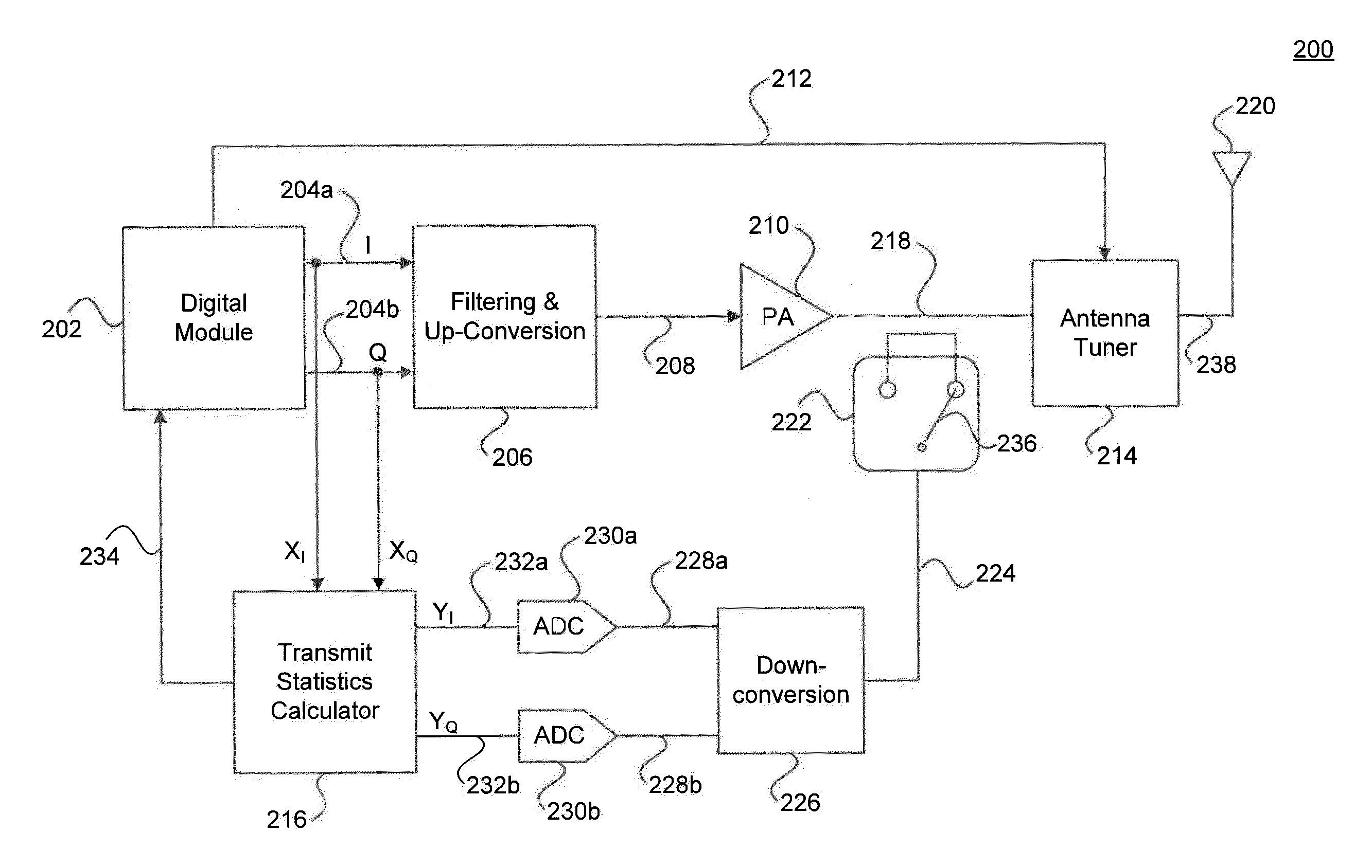
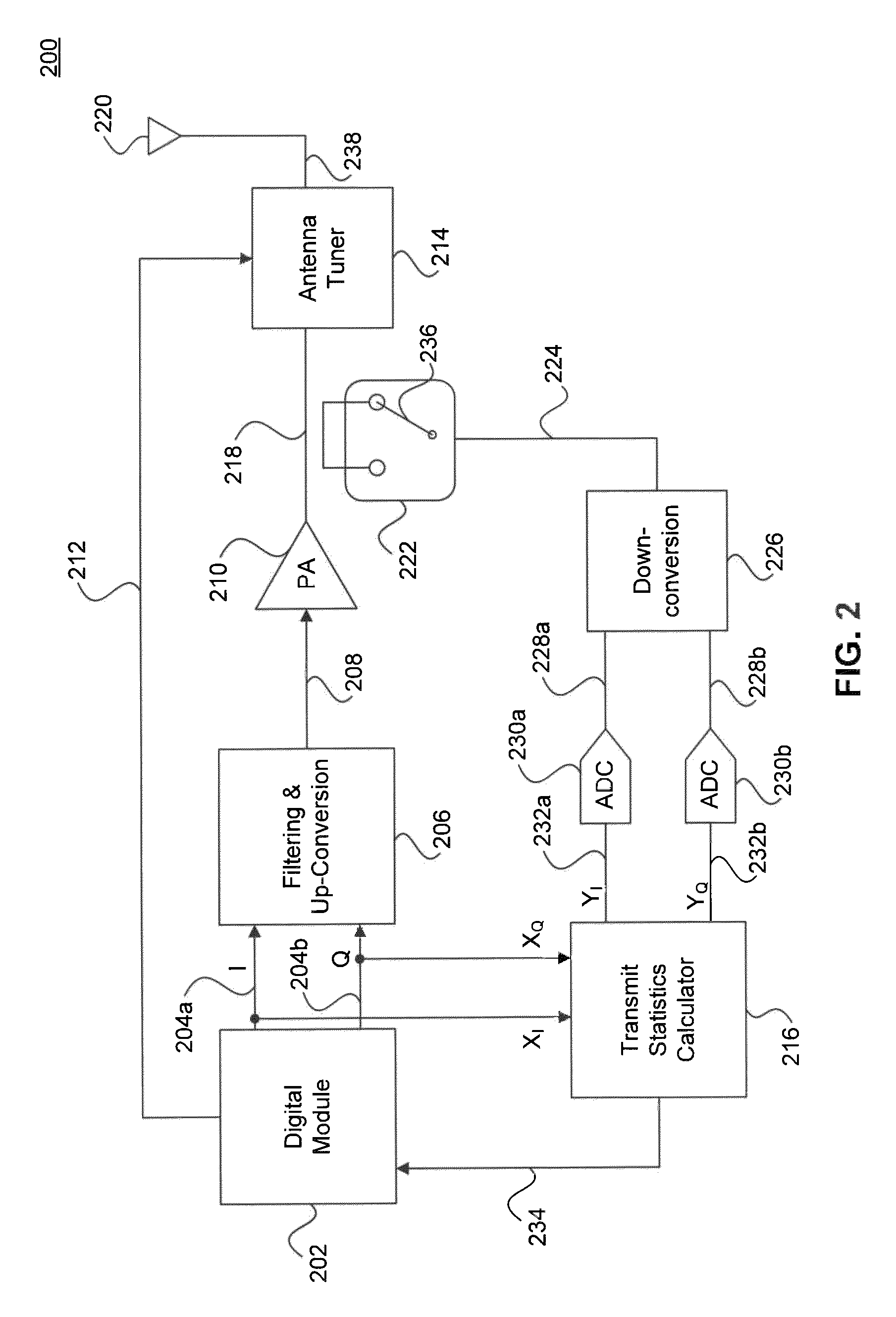
[0015]Typically, a power amplifier (PA) is designed to operate at its maximum efficiency for a known nominal load impedance, such as 50 Ohms, for example. However, when used in a wireless terminal, the PA may have to drive a load that varies in impedance over time. When impedance mismatch occurs, forward and reflected signals at the antenna feed point create a voltage standing wave, This reduces power transfer from the PA to the antenna. Conversely, the impedance mismatch at the antenna feed point also reduces the power transfer from the antenna to the receiver and degrades receiver sensitivity.

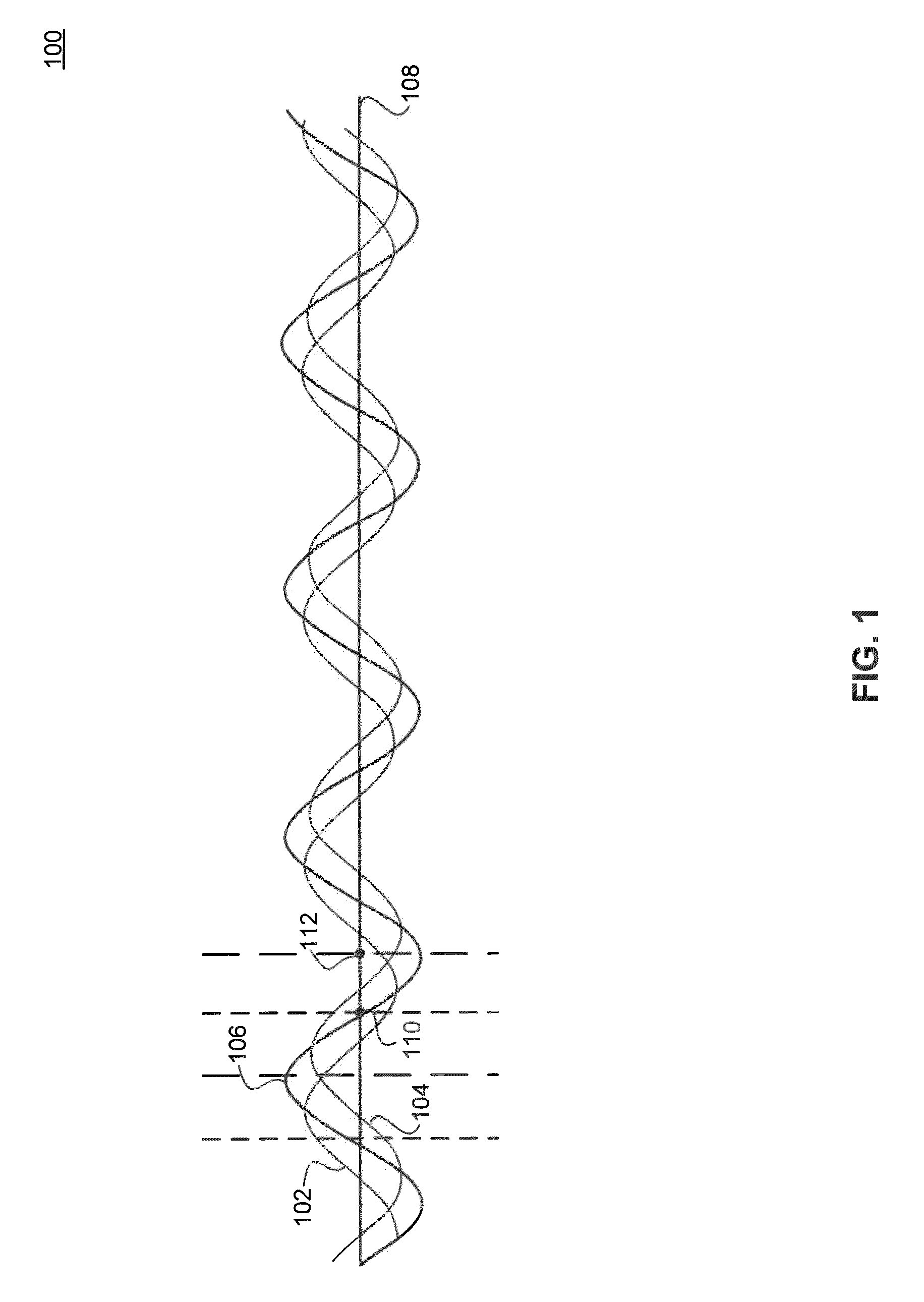
[0016]FIG. 1 is an example 100 that illustrates the formation of a standing wave 106 in a transmission line 108. As shown in FIG. 1, standing wave 106 is formed by a forward wave 102 and a reflected wave 104 combining with each other. Forward wave 102 may be the result of a voltage signal being transmitted at one end of transmission line 108. Reflected wave 104 results from forward wave 102 b...


PUM


Abstract

An antenna tuner is placed between a Power Amplifier (PA) and an antenna. The antenna tuner includes programmable components that can be tuned in order to effect an impedance translation between the antenna and the PA output. In an embodiment, the antenna tuner is adapted dynamically based on changes in the impedance of the antenna. In another embodiment, the antenna tuner is controlled based on measurement of the voltage reflection coefficient S11.

Description

CROSS-REFERENCE TO RELATED APPLICATIONS[0001]The present invention claims the benefit of U.S. Provisional Application No. 61 / 494,843, filed Jun. 8, 2011, and U.S. Provisional Application No. 61 / 611,729, filed Mar. 16, 2012, both of which are incorporated herein by reference in their entireties.BACKGROUND[0002]1. Field of the Invention[0003]The present invention relates generally to radio frequency (RF) transceivers.[0004]2. Background Art[0005]Typically, a power amplifier (PA) is designed to operate at its maximum efficiency for a known nominal load impedance, such as 50 Ohms, for example. However, when used in a wireless terminal, the PA may have to drive a load that varies in impedance over time. When impedance mismatch occurs, forward and reflected signals at the antenna feed point create a voltage standing wave. This reduces power transfer from the PA to the antenna. Conversely, the impedance mismatch at the antenna feed point also reduces the power transfer from the antenna to ...

Claims


Application Information

Patent Timeline
Patent Type & Authority Patents(United States)
IPC IPC(8): H04K1/02
CPCH04B1/40H04B1/0458H04B17/00H04B1/406
Inventor PARK, BONGSEOKFUJIMOTO, WILLIAMDAKSHINAMURTHY, SRIRAMANLORENZ, ROBERT
Owner AVAGO TECH INT SALES PTE LTD
Why Eureka
Eureka Blog
Learn More