Reaction analysis apparatus, recording medium, measurement system and control system
a technology of reaction analysis and measurement system, applied in the direction of electrical control, process and machine control, instruments, etc., can solve the problems of insufficient reproducibility of detection, inability to obtain detailed information on the reaction, so-called knocking, etc., to achieve high reproducibility, efficient information supply, and high reproducibility
- Summary
- Abstract
- Description
- Claims
- Application Information
AI Technical Summary
Benefits of technology
Problems solved by technology
Method used
Image
Examples
modified example 1
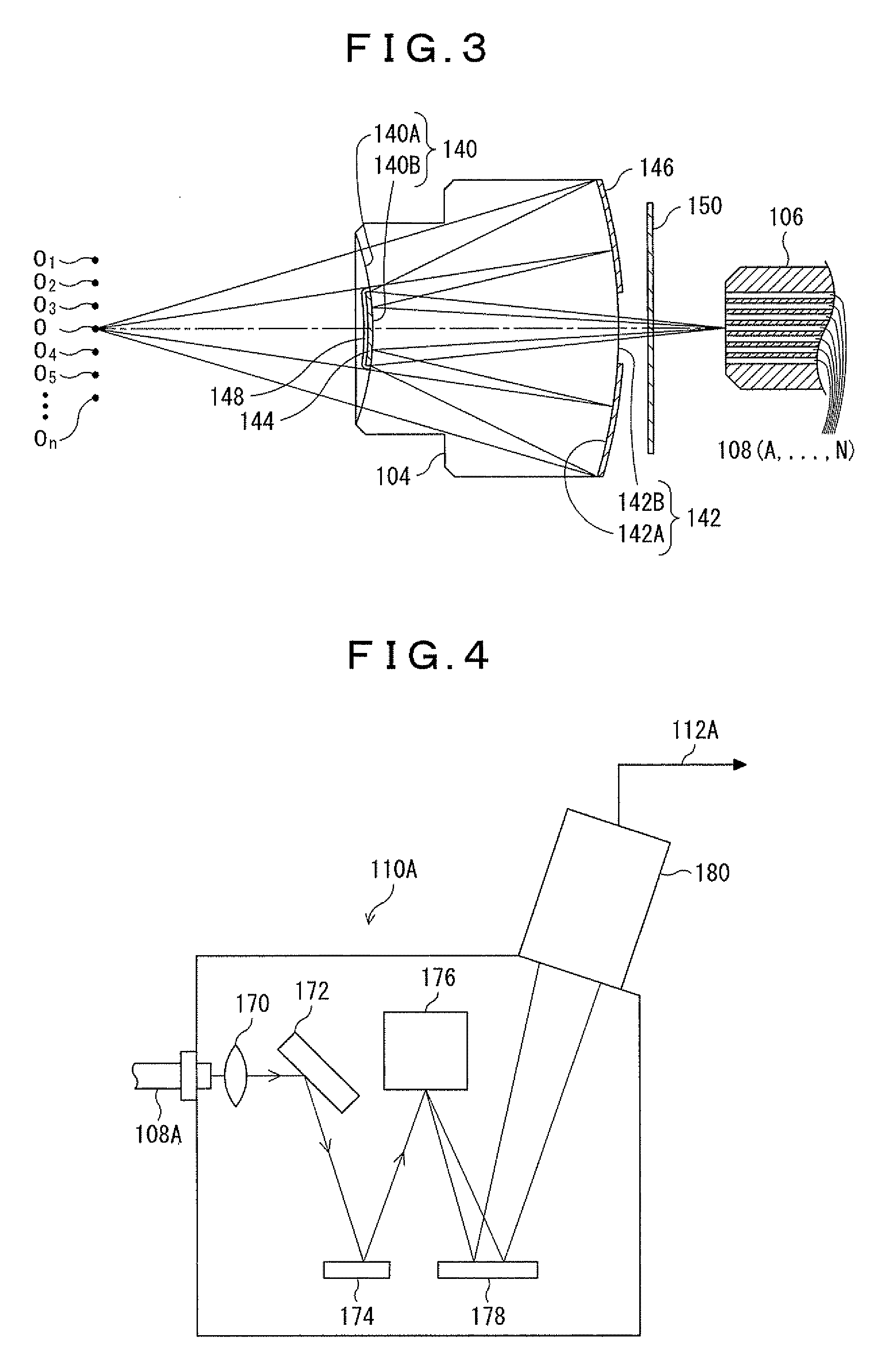
[0238]In the above embodiment, the optical element 104 is an optical system for focusing the light by reflection. However, an optical system, such as a convex lens, may be used instead of this optical element 104. Although, in this case, aberration due to the wavelength of the light is desirably reduced by various methods.
[0239]In the above embodiment, the end surfaces of the optical fibers 108A to 108N on the side of the optical element 104 are two-dimensionally arranged on the image formation surface of the optical element 104. However, the present invention is not limited to such an embodiment. The incident end surfaces of the optical fibers 108A to 108N may be three-dimensionally arranged. By this, it is possible to three-dimensionally measure and analyze the light emitted from the reaction region.
[0240]In the above embodiment, the spectrometers 112A to 112N perform spectrometry on the incident light and convert and output the spectral light obtained as a result into the electri...
modified example 2
Time Division Function of Measurement Result (Correspondence to Repeated Measurement, Multi-Point Measurement Unification and the Like)
[0253]FIG. 13 shows a schematic configuration of the measurement system according to the present embodiment.
[0254]This system is provided with the optical element 104, the optical fiber cable 106 and the reaction analysis apparatus 114 as well as FIG. 1, and a spectrometer 702 directly connected to the optical fiber cable 106 and a signal splitter 708 connected to the spectrometer 702 and the reaction analysis apparatus 114.
[0255]FIG. 14 shows an internal configuration of the spectrometer 702.
[0256]The spectrometer 702 has the same configuration as the spectrometer 110A shown in FIG. 4. However, the optical fiber cable 106 is directly connected to the spectrometer 702 instead of the optical fiber 108A to be connected to the spectrometer 110A. The optical fibers 108A to N are bundled in a row in the optical fiber cable 106. The optical fibers 108A to ...
modified example 3
Exceptional Processing Function in Case of Performing LIBS, SIBS or the Like
[0267]FIG. 17 shows a schematic configuration of a measurement system 900 in this embodiment.
[0268]In this measurement system 900, both the reaction such as the combustion, and plasma induction (breakdown) by laser are performed in the reaction region 102. In this measurement system 900, a processing selector 902 for selecting an output direction of the received signal in accordance with emission intensity of a specific wavelength component shown by the signal 704 is arranged on a signal path between the spectrometer 702 and the signal splitter 708 of the spectrometer 700 shown in FIG. 13.
[0269]The processing selector 902 outputs a signal of a predetermined period from a time point when light emission of the specific wavelength component (specifically, a wavelength component of laser beam) is detected (a period when the breakdown by laser is performed) as a signal 904, and outputs other signals to the signal...
PUM
| Property | Measurement | Unit |
|---|---|---|
| wavelength band | aaaaa | aaaaa |
| wavelength band | aaaaa | aaaaa |
| wavelength | aaaaa | aaaaa |
Abstract
Description
Claims
Application Information
 - R&D
- Intellectual Property
- Life Sciences
- Materials
- Tech Scout
- Unparalleled Data Quality
- Higher Quality Content
- 60% Fewer Hallucinations
Browse by: Latest US Patents, China's latest patents, Technical Efficacy Thesaurus, Application Domain, Technology Topic, Popular Technical Reports.
© 2025 PatSnap. All rights reserved.Legal|Privacy policy|Modern Slavery Act Transparency Statement|Sitemap|About US| Contact US: help@patsnap.com


