
Underground water retention system and associated methods

a water retention system and water technology, applied in water cleaning, sewage draining, water cleaning, etc., can solve the problems of inability to store significant amounts of water, inability to capture a large amount of water, and costing or unsightly, and achieve the effect of reducing the risk of contamination

Active Publication Date: 2014-06-17
ENVIRONMENTAL CONSERVATION SOLUTIONS LLC
View PDF8 Cites 0 Cited by
  • Summary
  • Abstract
  • Description
  • Claims
  • Application Information

AI Technical Summary

Benefits of technology

[0005]One object of the present invention is to receive water from any water source or collection device and store it in a unique underground pipe system that, in alternative embodiments, can also transport and / or distribute excess water into the ground. This system has an endless variety of potential residential and commercial applications, especially as, being stored underground, the water stored therein would not evaporate and could be stored indefinitely with little risk of contamination that can occur in stagnant water store above the ground.
[0006]Also, since one object of the present system is to reclaim water that has previously been fertilized or treated, the system can substantially reduce future costs by capturing that fertilized or treated water and allowing it to be re-used. The system can also be used to capture and collect storm water runoff from agricultural applications, allowing treatment before discharge. For this type of use, filtration medias or materials can also be added to the present invention to clean the sediment or remove pollutants.
[0007]The present invention accomplishes all of this without necessarily taking up valuable land space or being comprised of unsightly structures. The present invention also offers the alternative advantage of being able to be constructed using little or no rock and being able to operate completely passively, as some of its embodiments do not require any moving parts or electricity to operate, and therefore economically. Therefore, this invention can be constructed and operated more efficiently and economically.
[0015]In practice, in this embodiment of the invention, water preferably flows into the means for distribution only after a specific amount accumulates in the layers. This allows both a consistent amount of water to remain in the layers and provides time to allow the means for distribution to distribute the water into the ground.

Problems solved by technology

Commercially, there are also potentially limitless applications for a system capable of capturing and storing water for later use.
Heretofore, those who have desired to capture and store water have used costly or unsightly systems that occupy valuable land area and are not able to store significant amounts of water.
These systems all suffer from the disadvantages of occupying aboveground space on a piece of property and having the capacity to only store a relatively small amount of water.

Method used


Image

  • Underground water retention system and associated methods
  • Underground water retention system and associated methods
  • Underground water retention system and associated methods

Examples


Embodiment Construction

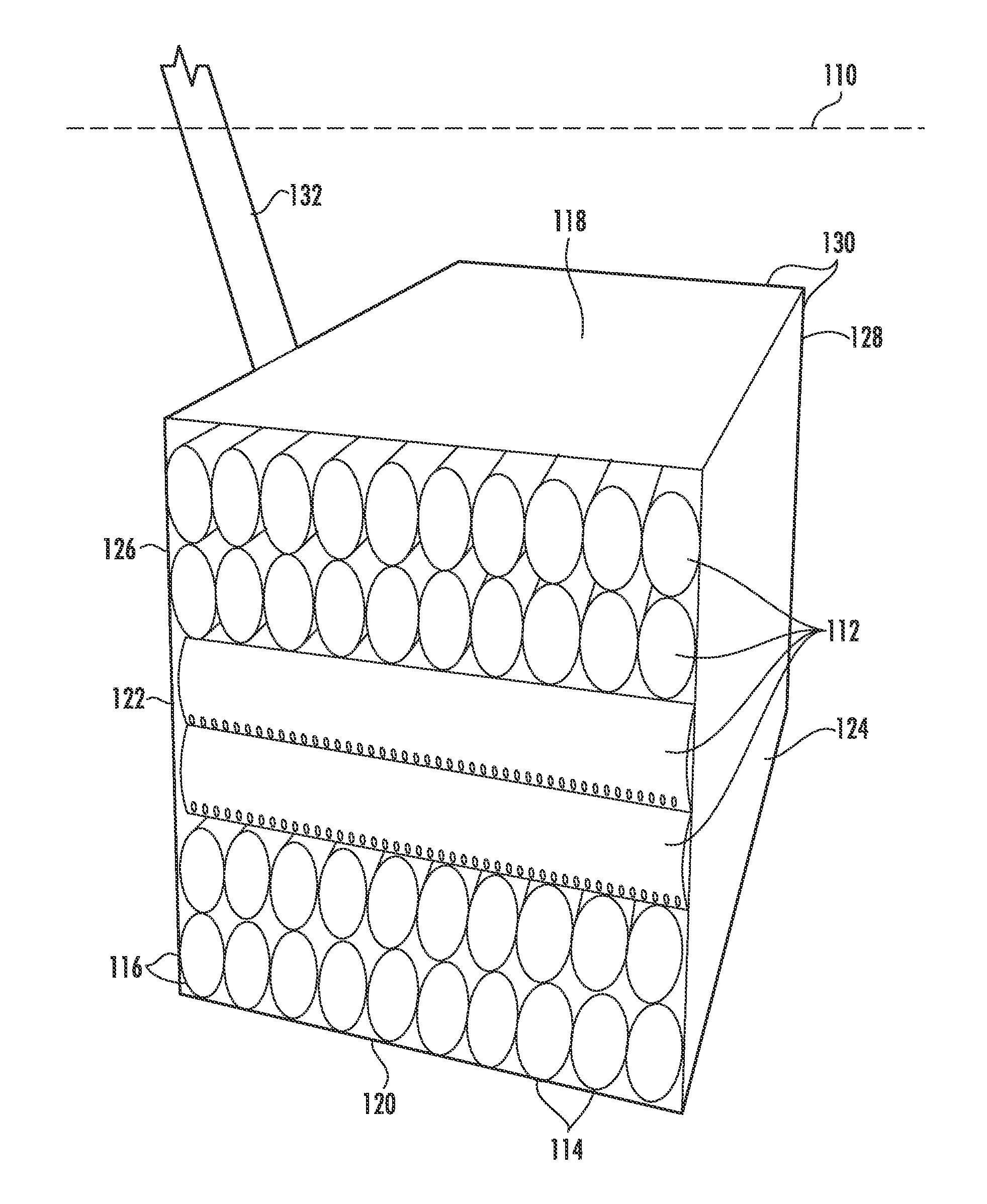
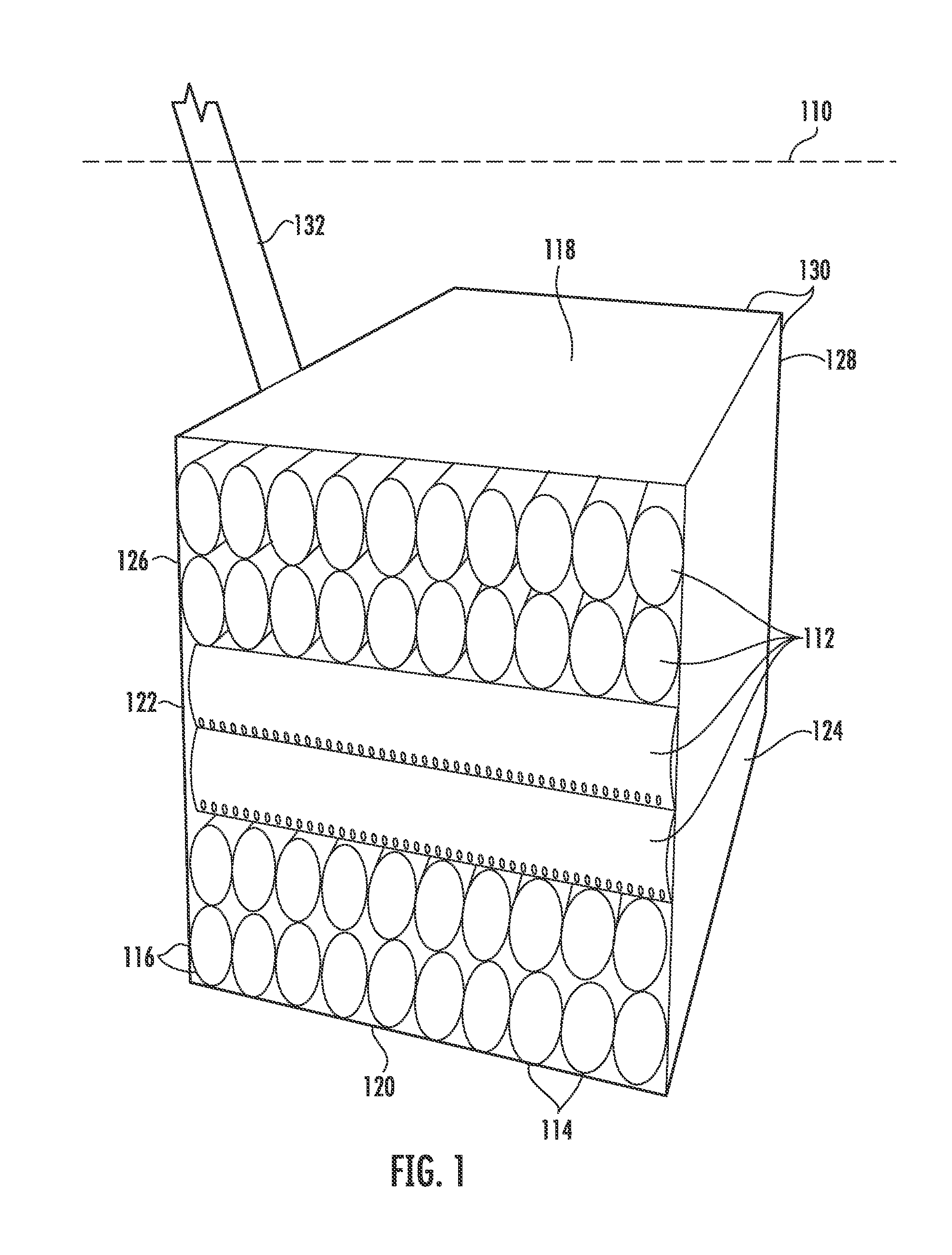
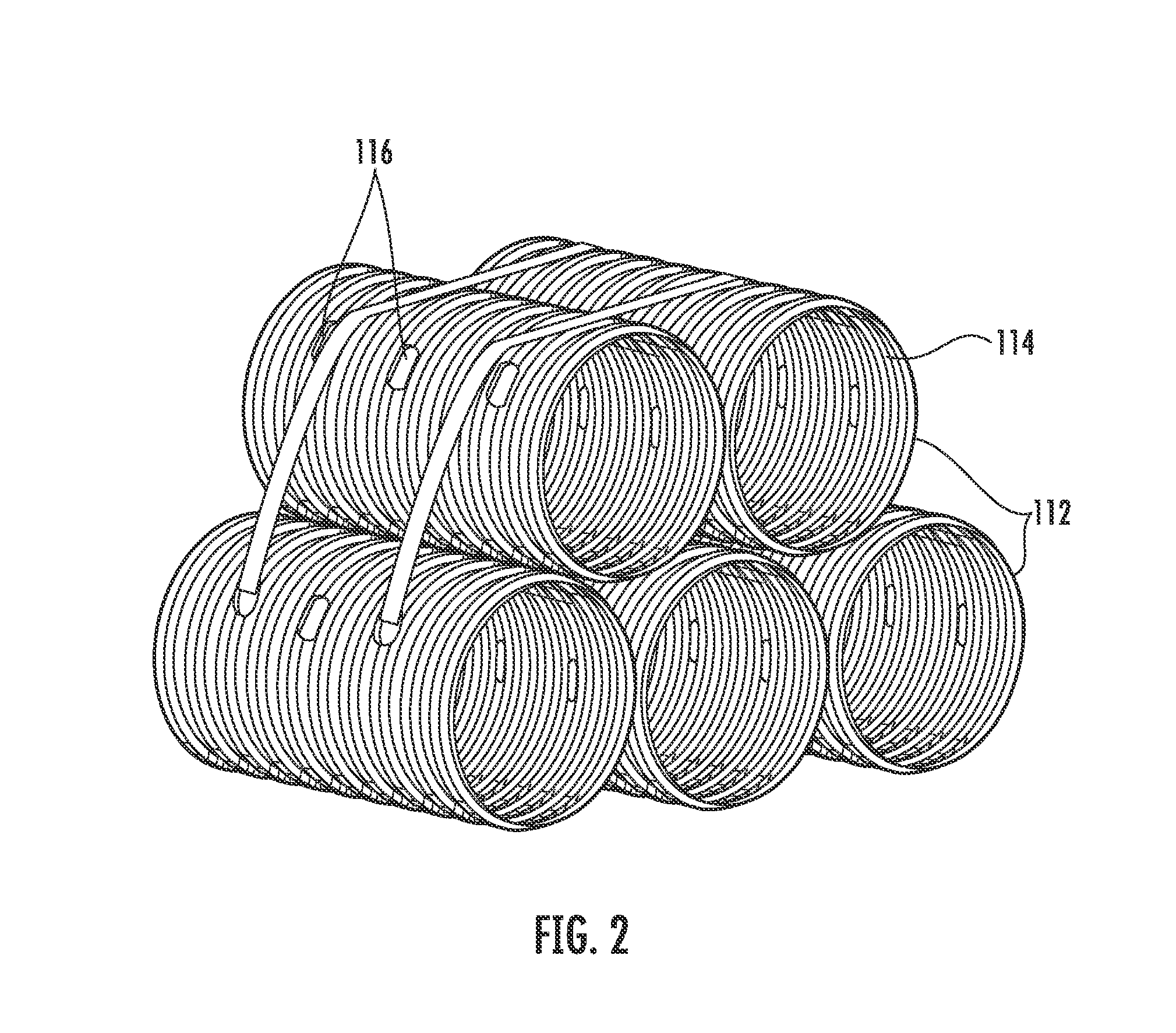
[0028]A description of embodiments of the present invention will be detailed herein with reference to FIGS. 1-5. The features that characterize the invention, both as to organization and method of operation, together with further objects and advantages thereof, will be better understood from the foregoing description considered in conjunction with the accompanying drawings. It should be noted that the drawings are for the purpose of illustration and description and are not intended as a definition of the limits of the invention. These and other objects attained, and advantages offered, by the present invention will become more fully apparent as the description that now follows is read in conjunction with the accompanying drawings.

[0029]Referring to FIGS. 1 and 2, according to an embodiment of the underground water retention system of the present invention, the system comprises an installation beneath the ground 110 at least one layer 112 of substantially cylindrical pipes 114 with a...


PUM


Abstract

A liquid retention system in accordance with an embodiment of the invention comprises a plurality of pipes having a wall defining a pipe conduit, at least some of the pipes having at least one hole through the wall for allowing liquid to enter the conduit. Each of two sets of pipe groups is arranged into a two layers of the pipes. The pipes in one layer are arranged in adjacent proximity along their lengths such that the walls of adjacent pipes define a plurality of gaps while the pipes in the second layer are at least partially seated in the gaps. The cylindrical axes of the pipes in the two pipe groups relative to one another are non-parallel. The pipe groups are arranged in a liquid retention portion, which is at least partially enclosed to retain liquid therein.

Description

CROSS-REFERENCE TO RELATED APPLICATION[0001]This is a continuation of application Ser. No. 12 / 545,291 filed Aug. 21, 2009, entitled “Underground Water Retention System and Associated Methods,” which is a continuation-in-part of application Ser. No. 12 / 147,722, filed Jun. 27, 2008, which claims the benefit of provisional application Ser. No. 60 / 947,060, filed Jun. 29, 2007. Each of these references is incorporated herein by reference in its entirety.FIELD OF THE INVENTION[0002]The present invention relates to a water retention system for use in an underground installation and associated methods.BACKGROUND OF THE INVENTION[0003]Water retention is essential for any number of varied applications. Whether there is excess rain or storm water that needs to be dealt with or water shortages, water regulation is necessary to preserve people's health, safety, and property. Commercially, there are also potentially limitless applications for a system capable of capturing and storing water for la...

Claims


Application Information

Patent Timeline
Patent Type & Authority Patents(United States)
IPC IPC(8): E02B11/00
CPCC02F1/004E03F1/005C02F2103/001E03B3/03Y02A20/108
Inventor EVERSON, DOUGLAS, G.
Owner ENVIRONMENTAL CONSERVATION SOLUTIONS LLC
Learn More