
Method and system for a dynamic transmission gain control using a dedicated power amplifier driver in a radio frequency transmitter

a technology of dynamic transmission and power amplifier, applied in the field of communication systems, can solve the problems of distorted and/or otherwise degraded transmission wireless signals, distortion and/or degradation,

Active Publication Date: 2014-06-10
AVAGO TECH INT SALES PTE LTD
View PDF19 Cites 3 Cited by
  • Summary
  • Abstract
  • Description
  • Claims
  • Application Information

AI Technical Summary

Problems solved by technology

The transmitted wireless signals may be distorted and / or otherwise degraded during transmission over the wireless medium.
The distortion and / or degradation may occur as a result of factors comprising channel impairments such as noise, signal interference, intersymbol interference and co-channel interference.

Method used


Image

  • Method and system for a dynamic transmission gain control using a dedicated power amplifier driver in a radio frequency transmitter
  • Method and system for a dynamic transmission gain control using a dedicated power amplifier driver in a radio frequency transmitter
  • Method and system for a dynamic transmission gain control using a dedicated power amplifier driver in a radio frequency transmitter

Examples


Embodiment Construction

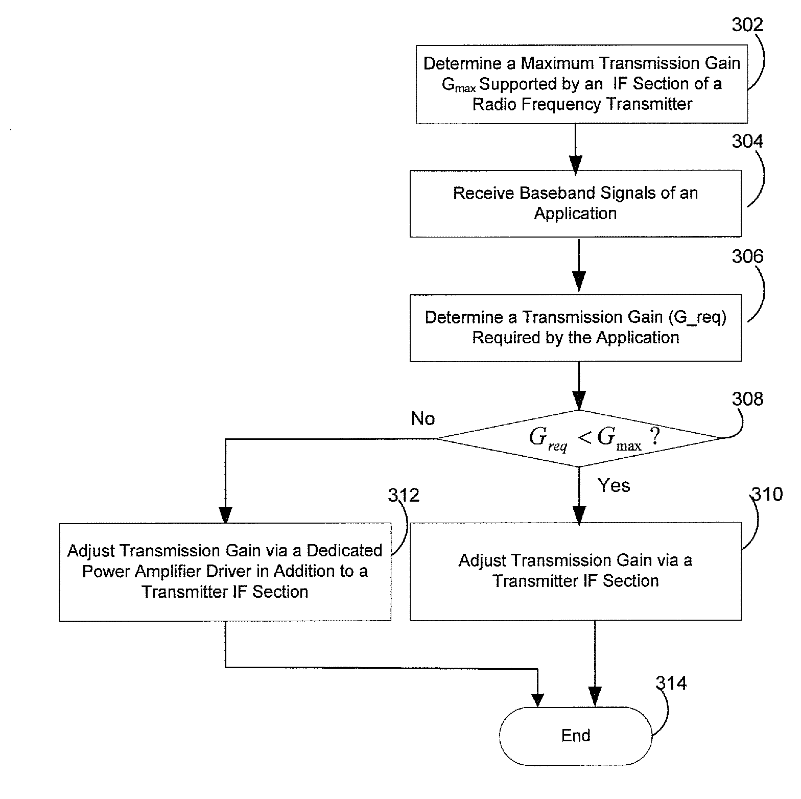
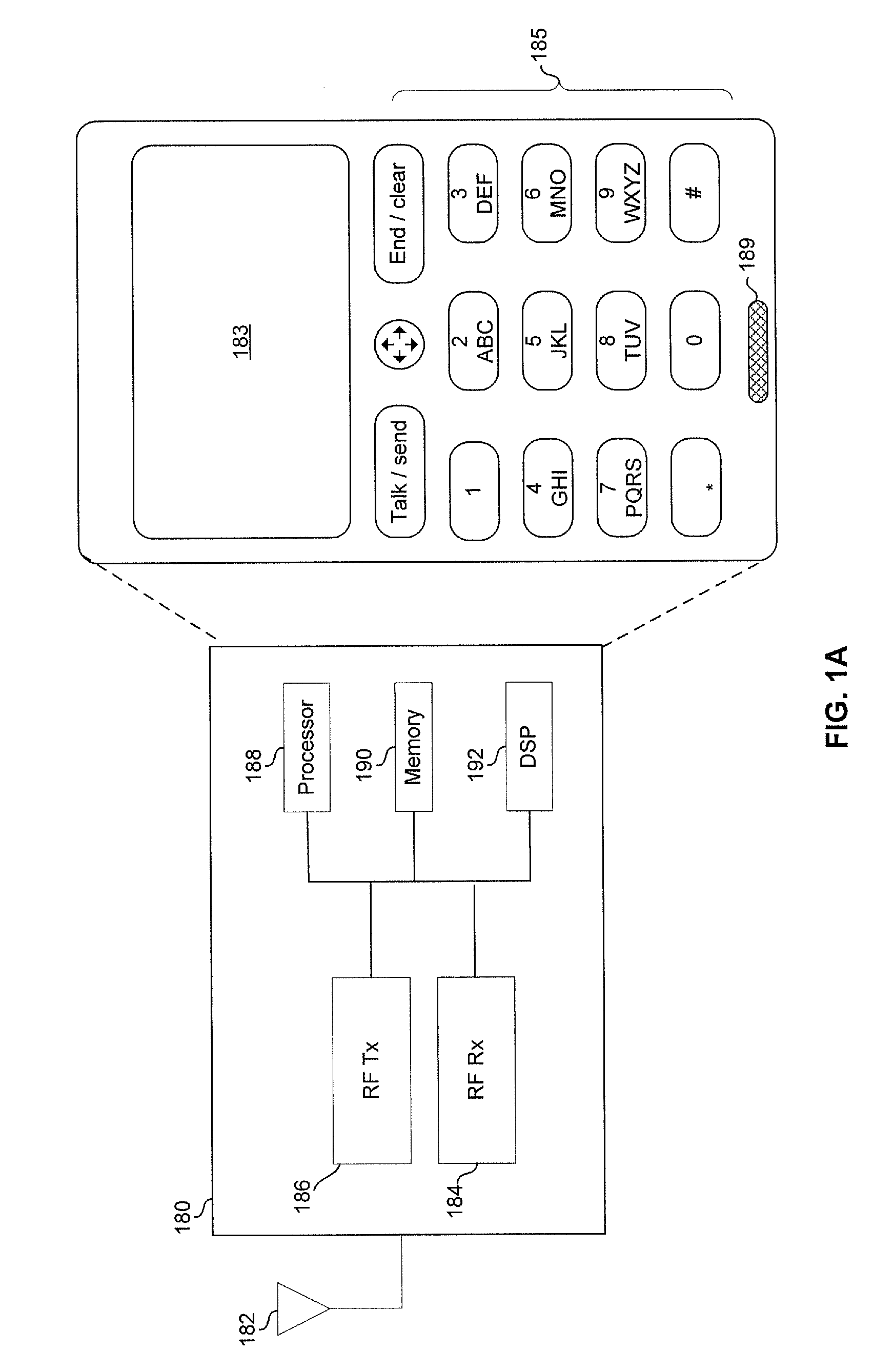
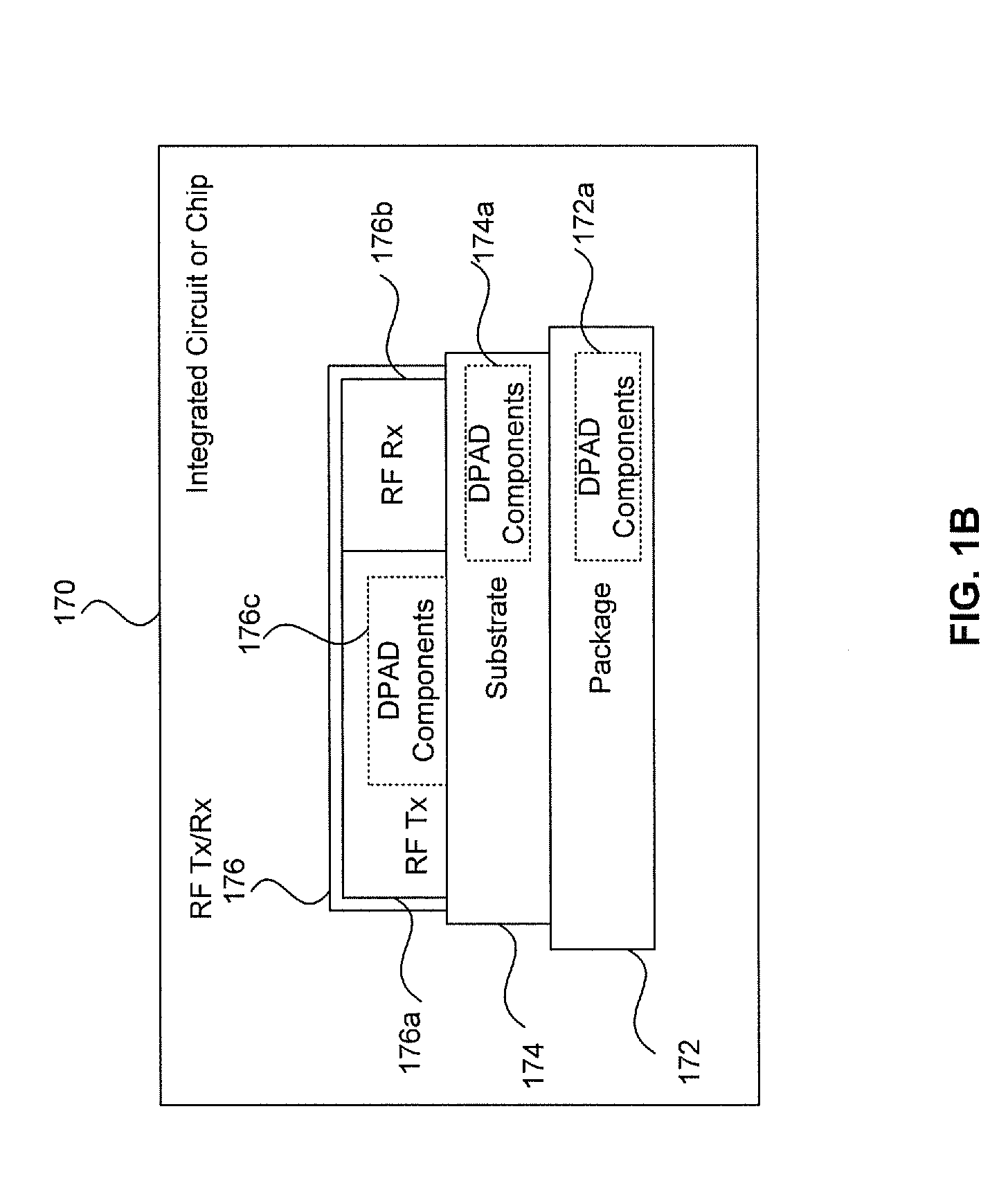
[0013]Certain embodiments of the invention may be found in a method and system for a dynamic transmission gain control using a dedicated power amplifier driver in a radio frequency transmitter. In accordance with various embodiments of the invention, a transmitter RF front-end is integrated on a single substrate and / or a chip. The transmitter RF front-end is enabled to determine whether an associated IF amplification stage is able to provide a required transmission gain for transmitting an output signal. The signal to be transmitted may comprise a baseband signal. A dedicated power amplifier driver may be configured to provide additional gain, when needed based on the determination, to meet the required transmission gain for transmitting the output signal. The associated IF amplification stage comprises an upconversion mixer and a lowpass filter (LPF). The upconversion mixer may be implemented as an active mixer or a passive mixer. The upconversion mixer may be enabled to operate in...


PUM


Abstract

A transmitter RF front-end integrated on a single substrate is enabled to determine whether associated IF amplification stage provides a required transmission gain for transmitting an output signal of an application. A dedicated power amplifier driver within the transmitter RF front-end is configured to provide additional gain, when needed based on the determination, to meet the required transmission gain for transmitting the output signal. The associated IF amplification stage comprises an upconversion mixer and a lowpass filter (LPF). The upconversion mixer may be implemented as an active mixer or a passive mixer. The upconversion mixer and the dedicated power amplifier driver are enabled to operate in 2.44 gigahertz. A maximum gain provided by the associated intermediate frequency (IF) amplification stage for transmitting the output signal is determined to decide the additional gain provided by the dedicated power amplifier driver by comparing with the required transmission gain.

Description

CROSS-REFERENCE TO RELATED APPLICATIONS / INCORPORATION BY REFERENCE[0001]Not applicable.FIELD OF THE INVENTION[0002]Certain embodiments of the invention relate to communication systems. More specifically, certain embodiments of the invention relate to a method and system for a dynamic transmission gain control using a dedicated power amplifier driver in a radio frequency transmitter.BACKGROUND OF THE INVENTION[0003]A wireless transmitter transmit wireless signals via a wireless medium and a wireless communication device comprising a receiver is operable to receive and recover the transmitted wireless signals from the wireless medium. The transmitted wireless signals may be distorted and / or otherwise degraded during transmission over the wireless medium. The distortion and / or degradation may occur as a result of factors comprising channel impairments such as noise, signal interference, intersymbol interference and co-channel interference. Accordingly, the transmitter is generally oper...

Claims


Application Information

Patent Timeline
Patent Type & Authority Patents(United States)
IPC IPC(8): H01Q11/12H04B1/04
CPCH03G3/3042H04B1/04H04B2001/0416
Inventor PAN, MENG-AN
Owner AVAGO TECH INT SALES PTE LTD
Learn More