Manufacturing device for permanent magnet disposed in rotating electrical machine and manufacturing method of the same
a technology of manufacturing device and permanent magnet, which is applied in the direction of auxillary welding device, magnetic body, paper/cardboard container, etc., and can solve the problems of limited motor performan
- Summary
- Abstract
- Description
- Claims
- Application Information
AI Technical Summary
Benefits of technology
Problems solved by technology
Method used
Image
Examples
first embodiment
[0025](First Embodiment)
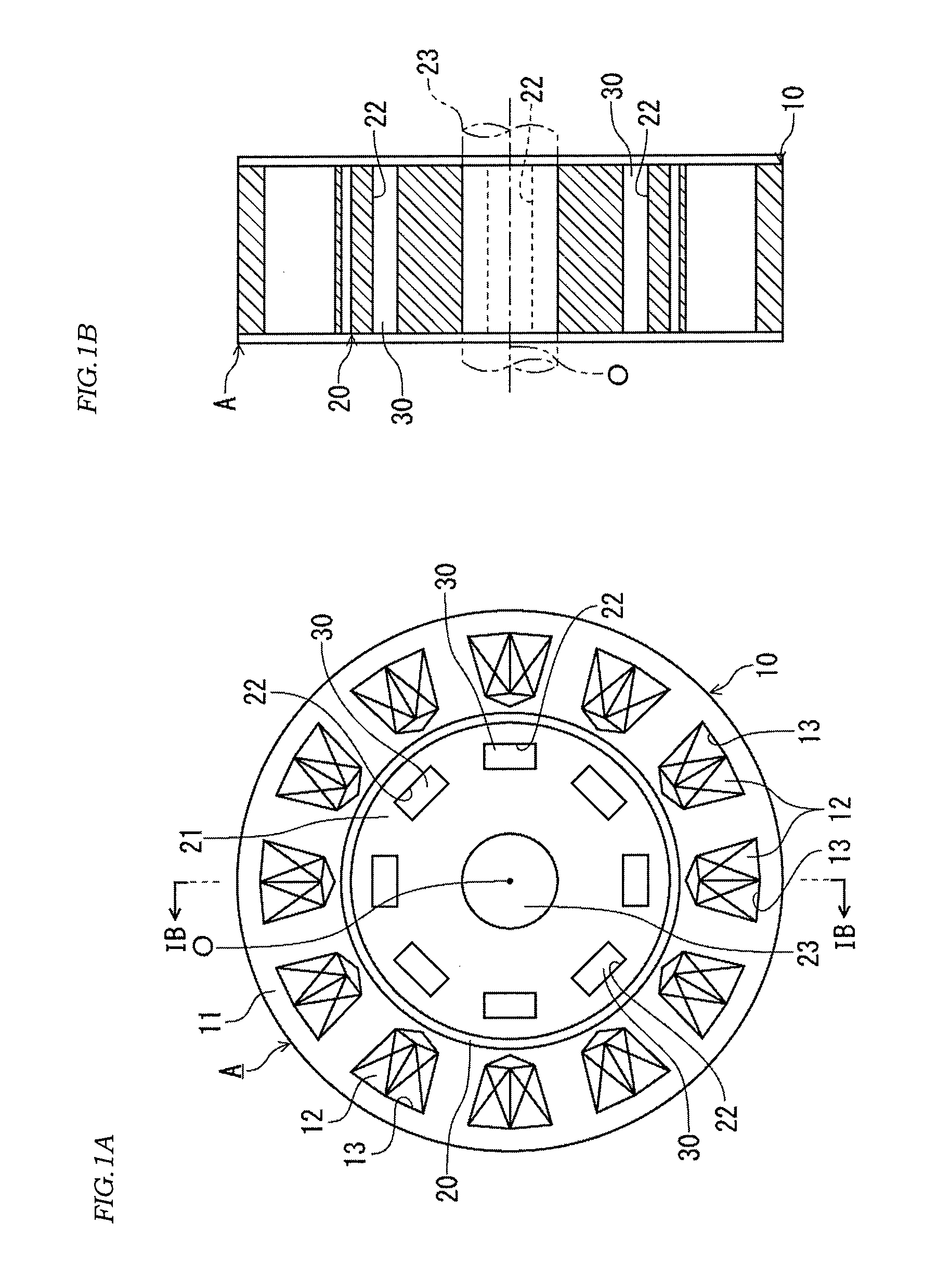
[0026]FIG. 1A is a front view illustrating an outline configuration of a rotating electrical machine to which a permanent magnet according to an embodiment of the present invention is applied. FIG. 1B is a sectional view along IB-IB line in FIG. 1A.
[0027]A permanent-magnet embedded rotating electrical machine A (hereinafter referred to simply as a “rotating electrical machine”) is formed of an annular stator 10 constituting a part of a casing, not shown, and a columnar rotor 20 arranged coaxially with this stator 10.
[0028]The stator 10 includes a stator core 11 and a plurality of coils 12. In the stator core 11, slots 13 are formed at equiangular intervals on the same circumference having a shaft center O at the center. The plurality of coils 12 are accommodated in the slots 13 formed in the stator core 11.
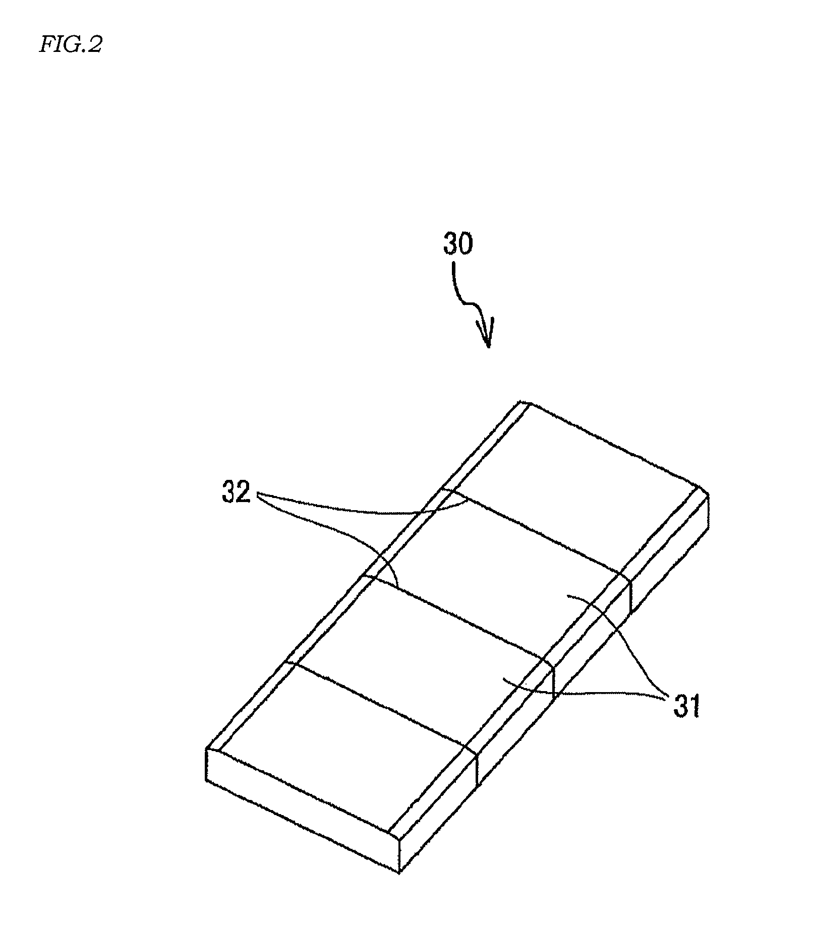
[0029]The rotor 20 includes a rotor core 21, a rotating shaft 23 rotating integrally with the rotor core 21, and a plurality of permanent magnets 30. In th...
second embodiment
[0073](Second Embodiment)
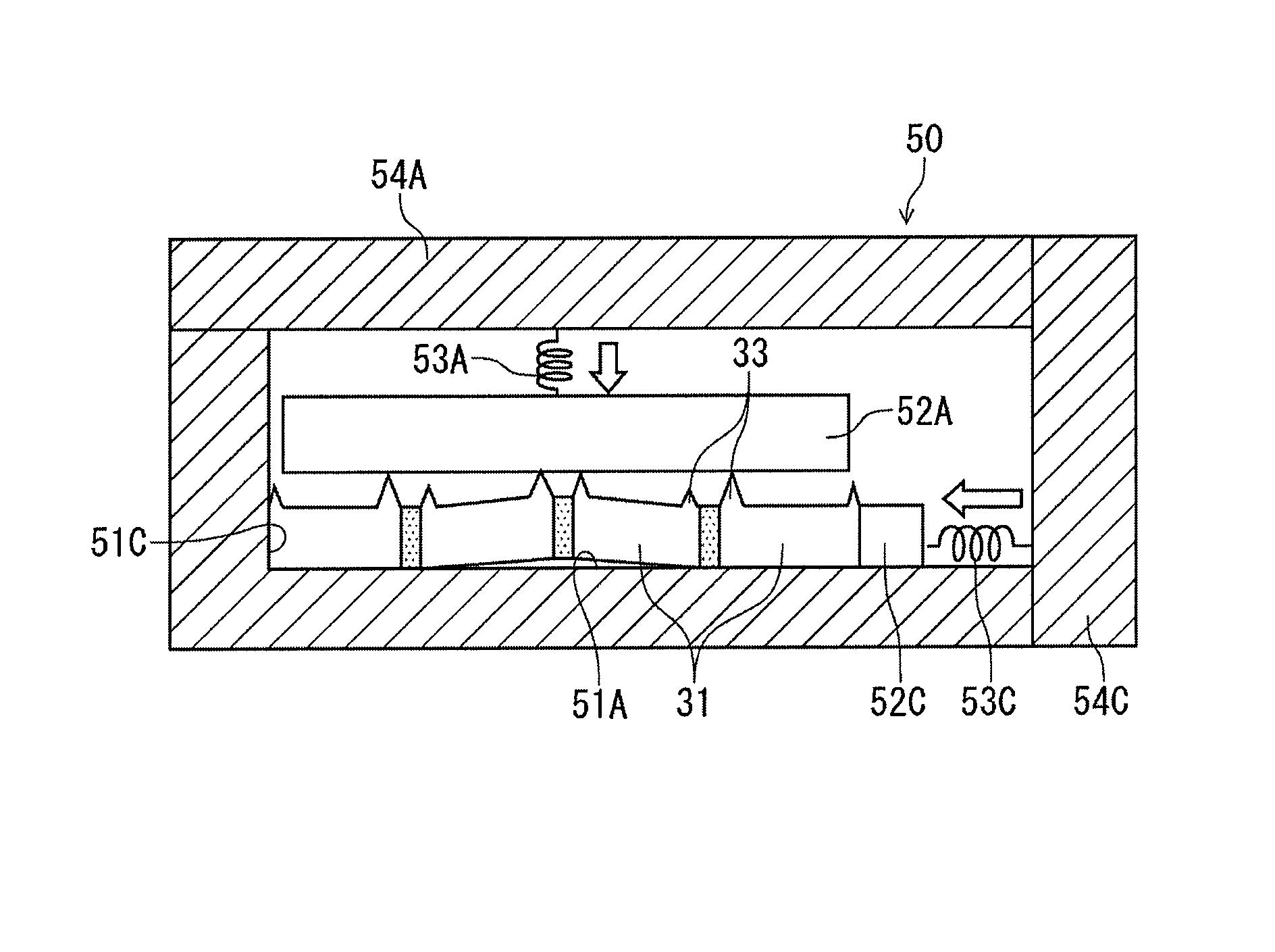
[0074]FIGS. 9 to 11 illustrate a second embodiment of a manufacturing device for a permanent magnet to be embedded in a rotor core of a rotating electrical machine to which the present invention is applied and a manufacturing method of the same. That is, FIG. 9 is a side view of an integrating jig, FIG. 10 is an explanatory diagram of a spring device used in the integrating jig, and FIG. 11 is a side view of an operation state of the integrating jig. In this embodiment, a configuration in which the pressing force to be imparted to at least either one of the thickness-direction movable member 52A and the width-direction movable member 52B is changed in accordance with an atmospheric temperature is added to the first embodiment. The same devices as those in the first embodiment are given the same reference numerals and the description will be omitted or simplified.
[0075]In the integrating jig 50 in this embodiment, the pressing force to be imparted to at least...
PUM
| Property | Measurement | Unit |
|---|---|---|
| heat resistance | aaaaa | aaaaa |
| temperature | aaaaa | aaaaa |
| temperature | aaaaa | aaaaa |
Abstract
Description
Claims
Application Information
 - Generate Ideas
- Intellectual Property
- Life Sciences
- Materials
- Tech Scout
- Unparalleled Data Quality
- Higher Quality Content
- 60% Fewer Hallucinations
Browse by: Latest US Patents, China's latest patents, Technical Efficacy Thesaurus, Application Domain, Technology Topic, Popular Technical Reports.
© 2025 PatSnap. All rights reserved.Legal|Privacy policy|Modern Slavery Act Transparency Statement|Sitemap|About US| Contact US: help@patsnap.com


