Liquid jet head and liquid jet apparatus
a liquid jet head and liquid jet technology, applied in the direction of printing, printing, printing circuit aspects, etc., can solve the problems of reducing production efficiency, increasing cost, wire corrosion, etc., and achieve the effects of reducing costs, improving production efficiency, and reducing restrictions on the structure of liquid jet heads
- Summary
- Abstract
- Description
- Claims
- Application Information
AI Technical Summary
Benefits of technology
Problems solved by technology
Method used
Image
Examples
first embodiment
[0047](First Embodiment)
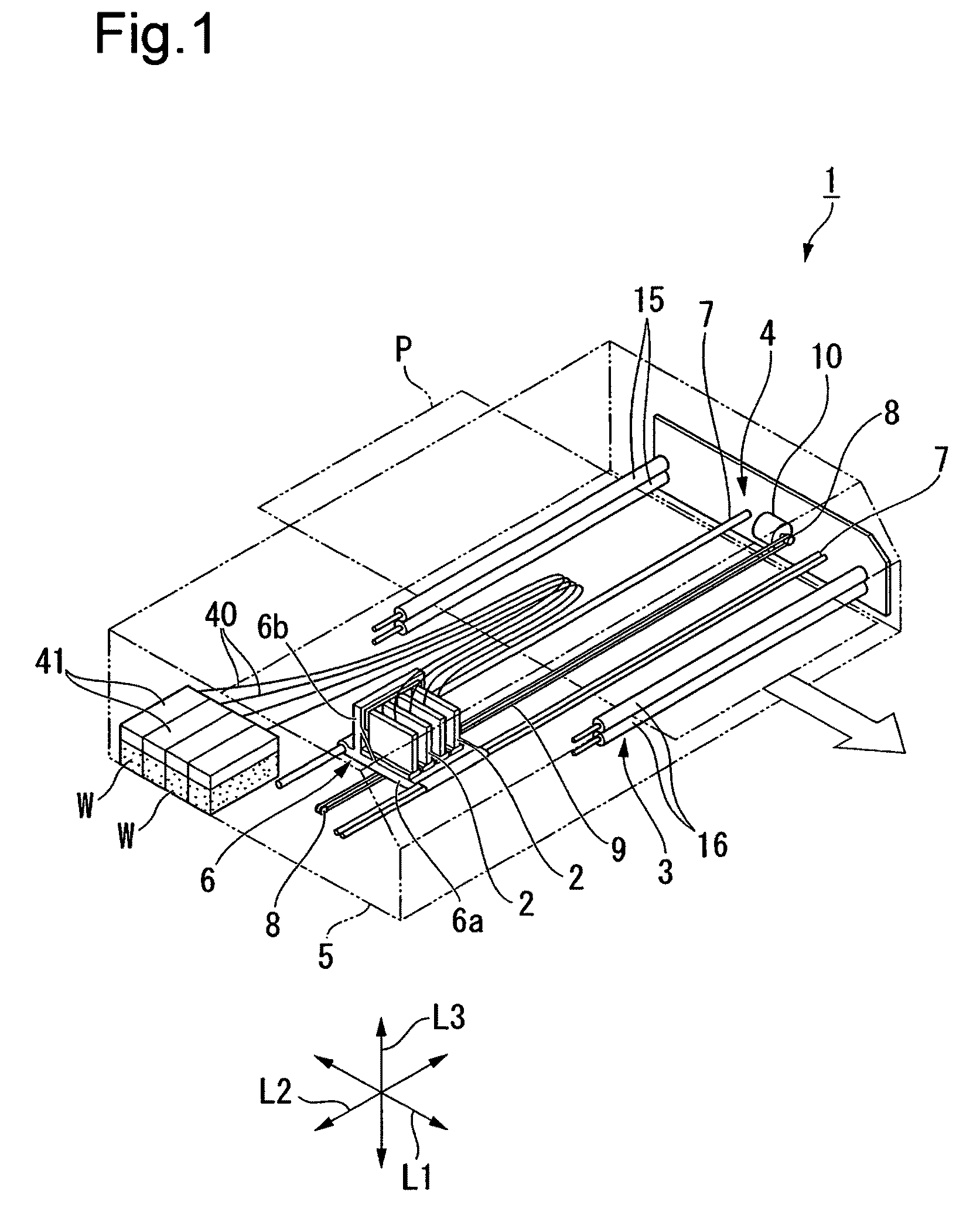
[0048]A first embodiment of the invention is described with reference to FIG. 1 to FIG. 6.
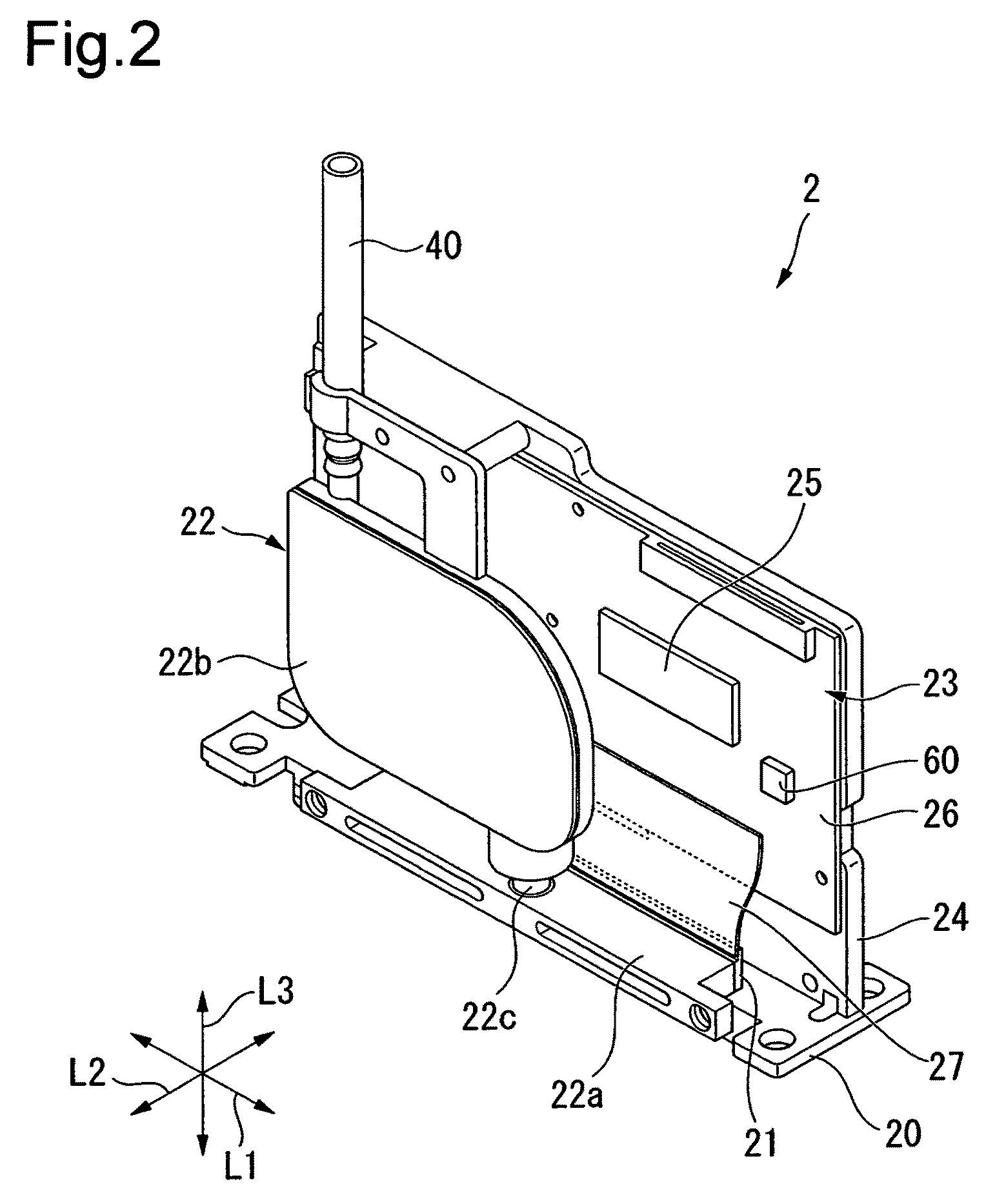
[0049]As illustrated in FIG. 1, the inkjet printer 1 according to this embodiment includes a plurality of ink jet heads (liquid jet heads) 2 for discharging the ink W, transfer means 3 for transferring recording paper (recording medium) P in a predetermined direction of the arrow L1 (transfer direction), and moving means 4 for reciprocating the plurality of ink jet heads 2 in a direction of the arrow L2 (scan direction) which is orthogonal to the transfer direction.
[0050]More specifically, the ink jet printer 1 is a printer of a so-called shuttle type which records text or an image on the recording paper P while transferring the recording paper P in the transfer direction and moving the ink jet heads 2 in the scan direction which is orthogonal to the transfer direction.
[0051]It is to be noted that, in this embodiment, a case in which four ink jet heads 2 for discharging ...
second embodiment
[0106](Second Embodiment)
[0107]Next, a second embodiment is described with reference to FIG. 7.
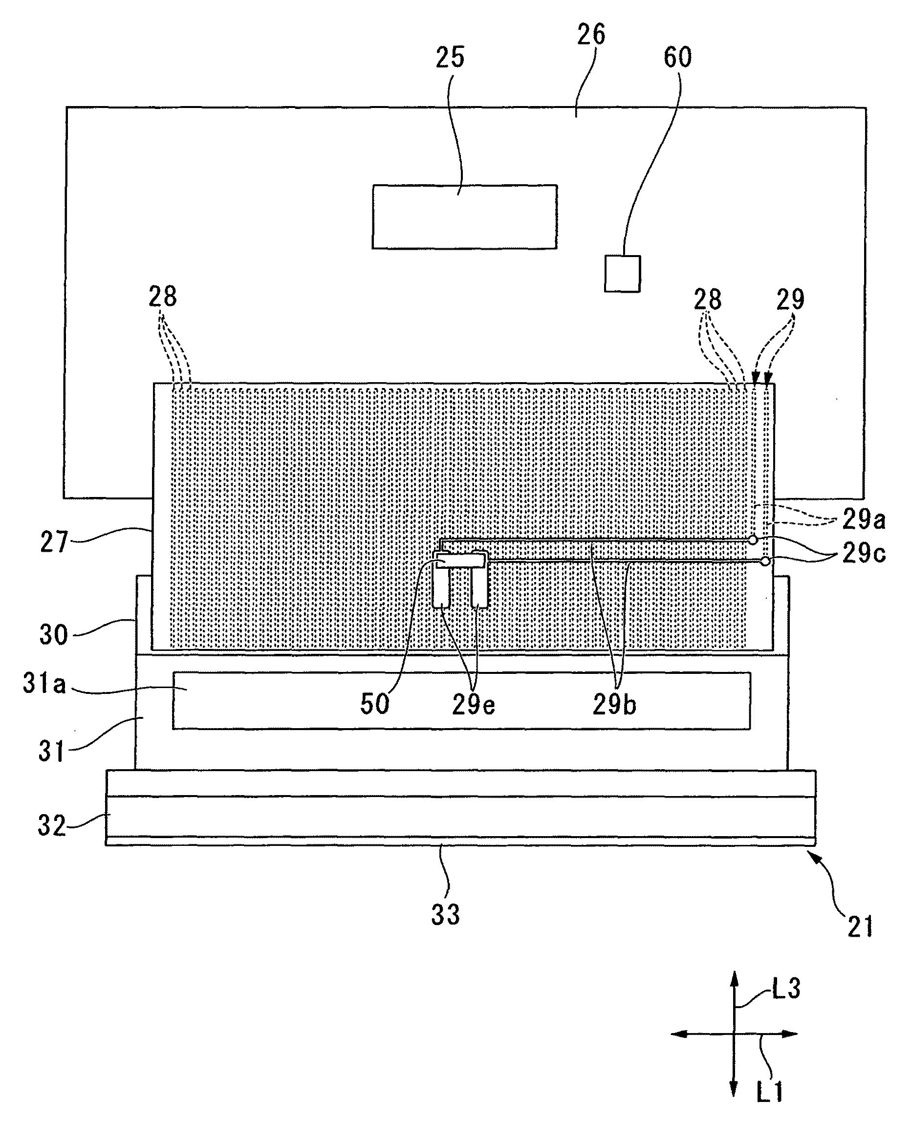
[0108]It is to be noted that this embodiment is different from the first embodiment in the structure of lands 29e which are formed on the flexible printed board 27, but other structures are similar to those of the first embodiment. Therefore, in this embodiment, only the lands 29e are described and description of structures which are similar to those of the first embodiment is omitted.
[0109]As illustrated in FIG. 7, the lands 29e are provided so as to extend from the middle portion of the flexible printed board 27 to a connecting end portion on the head chip 21 side of the flexible printed board 27. More specifically, the lands 29e are extended downward, and one end portions of the lands 29e are arranged at the middle portion of the flexible printed board 27 which is located between the head chip 21 and the drive circuit board 26, while the other end portions of the lands 29e are arranged ...
third embodiment
[0111](Third Embodiment)
[0112]Next, a third embodiment is described with reference to FIG. 8.
[0113]It is to be noted that, according to this embodiment, a heat conductive resin 29f is applied to the temperature sensor 50, but other structures of this embodiment are similar to those of the first embodiment . Therefore, in this embodiment, only the heat conductive resin 29f is described and description of structures which are similar to those of the first embodiment is omitted.
[0114]As illustrated in FIG. 8, the heat conductive resin 29f is applied to the temperature sensor 50 which is packaged on the flexible printed board 27. As the heat conductive resin 29f, for example, a resin the main component of which is heat conductive silicone or the like may be used. The heat conductive resin 29f is applied so as to cover the whole temperature sensor 50. Further, the heat conductive resin 29f is provided so as to extend from the middle portion of the flexible printed board 27 to the connect...
PUM
 Abstract
Description
Claims
Application Information
 - R&D
- Intellectual Property
- Life Sciences
- Materials
- Tech Scout
- Unparalleled Data Quality
- Higher Quality Content
- 60% Fewer Hallucinations
Browse by: Latest US Patents, China's latest patents, Technical Efficacy Thesaurus, Application Domain, Technology Topic, Popular Technical Reports.
© 2025 PatSnap. All rights reserved.Legal|Privacy policy|Modern Slavery Act Transparency Statement|Sitemap|About US| Contact US: help@patsnap.com


