Force increasing self-locking drill chuck and self-locking mechanism thereof

a self-locking, drill chuck technology, applied in the field of drill chucks, can solve the problems of unfavorable design of the overall the inability of the jaws to firmly clamp the tool handle, and the inability to use the structural design of the drill chuck in the design of the drill chuck

Active Publication Date: 2014-06-03
SHANDONG WEIDA MASCH CO LTD
View PDF18 Cites 9 Cited by
  • Summary
  • Abstract
  • Description
  • Claims
  • Application Information

AI Technical Summary

Problems solved by technology

For the drill chucks of the above structure, as the threads between the jaws and the nut produce great contact stress under working load, which renders great friction from relative sliding, the clamping force for clamping a tool handle created by the thread transmission between the nut and the jaws is not large enough, which results in that the jaws cannot firmly clamp the tool handle under the operation condition of large load and vibration, and thus there exists a hidden trouble of looseness.
However, the inventors of the present invention note that in the above drill chucks, adopting the common ratchet wheel pawl self-locking mechanism will bring trouble to the overall design of the drill chucks, including, but not limited to, that using the common ratchet wheel pawl self-locking mechanism will render the structural design of the drill chuck unreasonable or render it unable to be used in the design of the drill chucks.

Method used


Image

  • Force increasing self-locking drill chuck and self-locking mechanism thereof
  • Force increasing self-locking drill chuck and self-locking mechanism thereof
  • Force increasing self-locking drill chuck and self-locking mechanism thereof

Examples


first embodiment

The First Embodiment

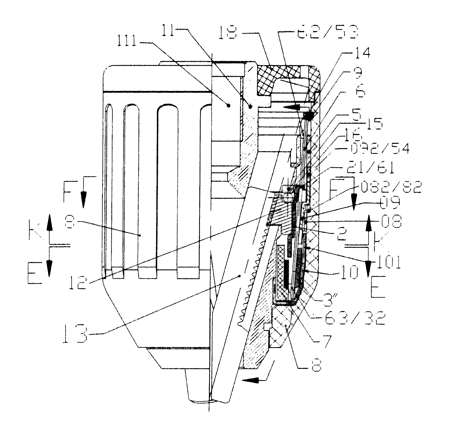
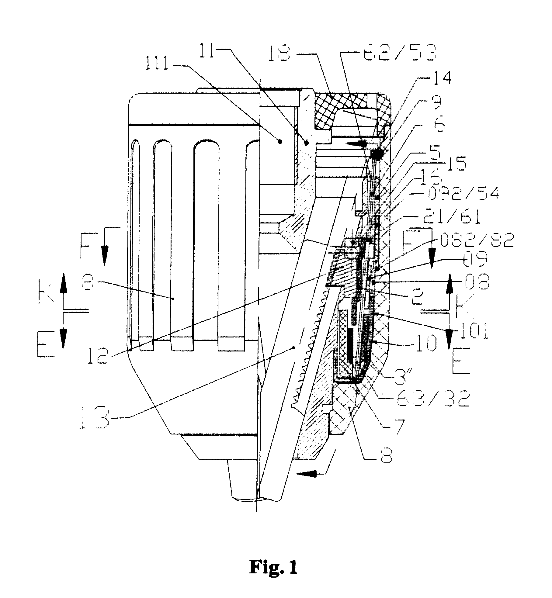
[0065]FIGS. 1 to 8b illustrate a force increasing self-locking drill chuck according to the first embodiment of the present invention. Wherein, the assembling of respective assemblies is described as follows:

[0066]as shown in FIG. 1, three jaws 13 are mounted within three slanting holes of the chuck body 11 forming an acute angle with respect to the base axis; two split-body nuts 12 are assembled on the chuck body 11 and engage with the threads of the three jaws, the split-body nuts and the outer nut sleeve 2 are assembled integrally by interference.

[0067]The rear cover 18 is fixedly mounted at the rear end of the chuck body 11, and the coat 8 is axially positioned on the chuck body via the clamp spring 14 and the washer 9. The clutch tooth sleeve 10 is fixed at the front end of the chuck body 11.

[0068]The driving member 5 is rotatably put around the chuck body 11, and the force bearing member 3″ and the shaft sleeve 7 are also rotatably put around the chuck body...

second embodiment

The Second Embodiment

[0092]FIGS. 9 to 14 illustrate a self-locking drill chuck according to the second embodiment of the present invention, and being different from the first embodiment, in the second embodiment the lever 6, the driving member 5 and the force bearing element 3″ are removed.

[0093]The assembling of respective assemblies of the self-locking drill chuck according to the present invention is described hereinafter in conjunction with FIGS. 9 to 14.

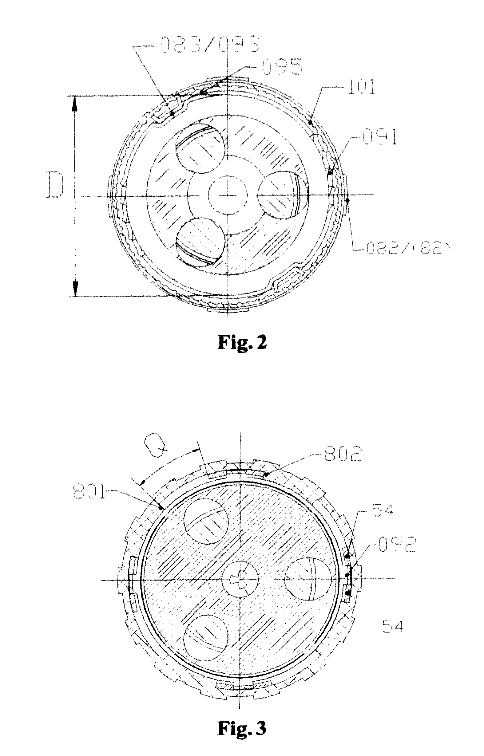
[0094]As shown in FIGS. 9 to 14, the nut sleeve includes a key 202, the key 082 of the control sleeve 08 is assembled within the groove between the groove side walls 801 and 802 of the coat, and the control sleeve 08 rotates synchronously with the coat; the key 202 of the nut sleeve and the key 092 of the oval deformation ring are located between the groove side walls 802 and 801 of the coat and can rotate by the angle Q with respect to the coat.

[0095]As shown in FIGS. 10 and 13, in the state that the coat can rotate freely and ...

third embodiment

The Third Embodiment

[0104]FIGS. 15 to 17 illustrate a self-locking drill chuck according to the third embodiment of the present invention.

[0105]Being different from the second embodiment, in the third embodiment, the nut sleeve 2 and the oval deformation ring 09 in the second embodiment are formed integrally as the oval deformation ring 09″, that is, the rear portion (the function of a nut sleeve) of the oval deformation ring 09″ integrally fastens the split-body nuts 12, and thus the split-body nuts 12 are positioned at the chuck body, with the restoration groove 093, the positioning portion 095 and the teeth 091 formed at the front portion.


PUM


Abstract

The present invention discloses a self-locking mechanism for use in a drill chuck, comprising: clutch tooth sleeves, fixedly connected with the chuck body of the drill chuck and forming teeth; an oval deformation ring, having a substantially circular first shape and a substantially oval second shape, wherein the oval deformation ring has teeth on the side wall, with the teeth engaging with the teeth of the clutch tooth sleeve when the oval deformation ring is in the second shape; and a control sleeve, for controlling the conversion of the oval deformation sleeve between the first shape and the second shape. The present invention also discloses a force increasing self-locking drill chuck with said self-locking mechanism. The self-locking mechanism according to the present invention can be used in drill chucks of multiple structures, and provides a brand-new thought for the designs of the self-locking mechanisms of drill chucks.

Description

FIELD OF THE INVENTION[0001]The present invention relates to a drill chuck, and also relates to a self-locking mechanism for drill chucks.BACKGROUND OF THE INVENTION[0002]Current drill chucks generally consist of a drill body, jaws, a nut, a bearing and a coat, wherein the drill body is connected with a transmission shaft of a power source, three jaws are respectively mounted within three equally distributed slanting holes in the drill body, the jaws have threads thereon which form thread transmission with the nut, and when the coat connected with the nut is rotated, the jaws can move along the slanting holes with respect to the drill body, thereby clamping or loosening a tool handle.[0003]For the drill chucks of the above structure, as the threads between the jaws and the nut produce great contact stress under working load, which renders great friction from relative sliding, the clamping force for clamping a tool handle created by the thread transmission between the nut and the jaw...

Claims


Application Information

Patent Timeline
Patent Type & Authority Patents(United States)
IPC IPC(8): B23B31/165B23B31/12
CPCB23B2231/38B23B31/1238B23B31/123Y10T279/32Y10T279/34Y10T279/17632
Inventor ZHOU, ZEXINLI, GUIJIE
Owner SHANDONG WEIDA MASCH CO LTD
Why Eureka
Try Eureka