
Automatic blade slope control system

Active Publication Date: 2014-05-27
TOPCON POSITIONING SYST INC
View PDF29 Cites 27 Cited by
  • Summary
  • Abstract
  • Description
  • Claims
  • Application Information

AI Technical Summary

Benefits of technology

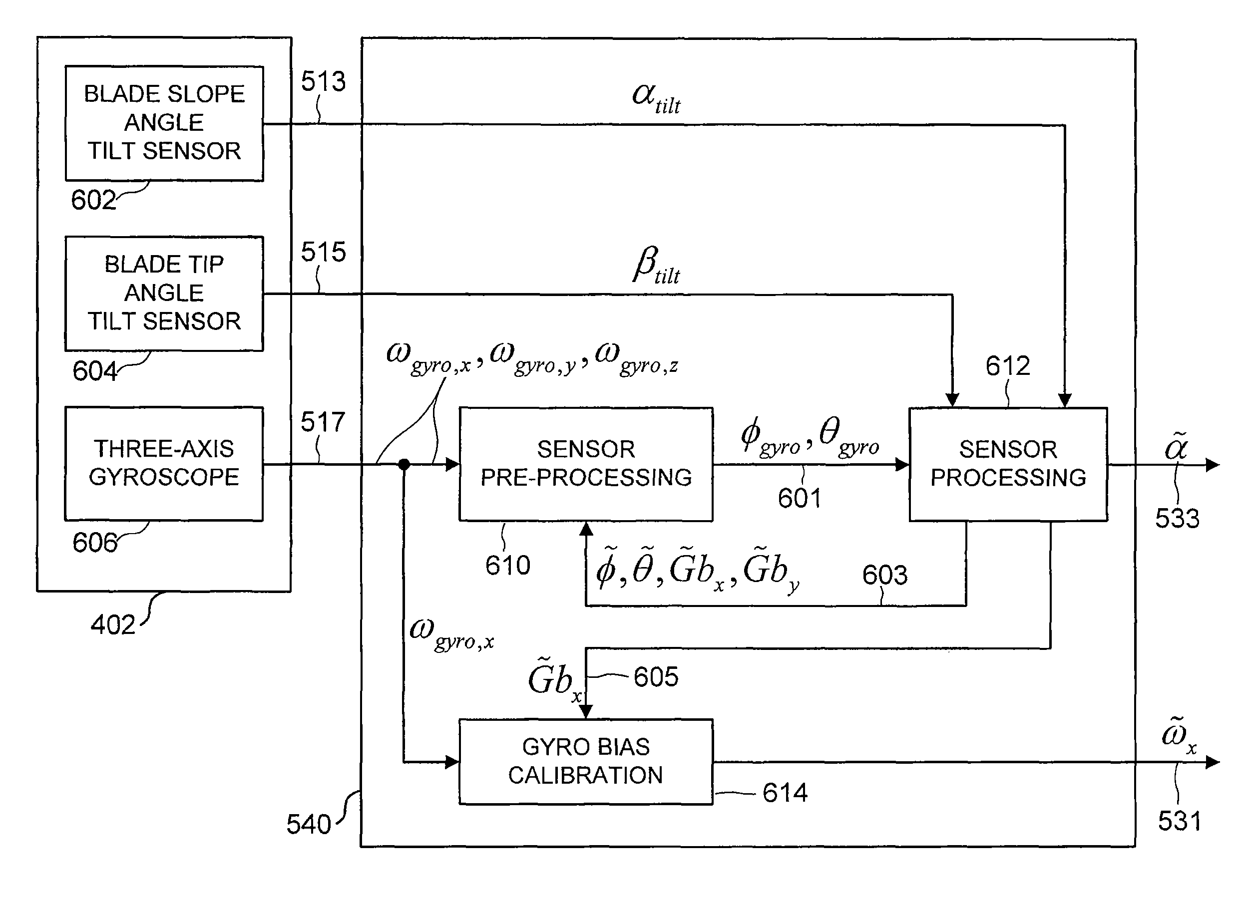
The patent describes a system that automatically controls the angle of a blade on a vehicle using measurements from a three-axis gyroscope and two tilt sensors. The measurements from the two sensors are fused together using algorithms that account for the time sequence of the measurements. The blade angle is computed from the fused measurements and controls the blade's movements using a proportional-derivative control algorithm or a proportional control algorithm. The data processing and control algorithms can be stored as computer-exchangeable code and executed by a computational system to control the blade angle. This invention allows for more accurate and precise control of the blade angle, improving the vehicle's stability and efficiency.

Problems solved by technology

A measurement from a tilt sensor is also not fused with measurements from the three-axis gyroscope if the measurement from the tilt sensor is invalid due to mechanical disturbances.

Method used


Image

  • Automatic blade slope control system
  • Automatic blade slope control system
  • Automatic blade slope control system

Examples


Embodiment Construction

[0019]Earthmoving machines, such as bulldozers and motor graders, are equipped with a blade to move earth. The blade position and blade attitude are controlled to shape the ground to a desired profile. The blade position and blade attitude can be controlled manually by a machine operator or automatically by an automatic blade control system. Combinations of manual and automatic control are often used. The blade parameters placed under automatic control are dependent on the application, type of earthmoving machine, desired precision, response time, and the complexity and cost of the automatic control system.

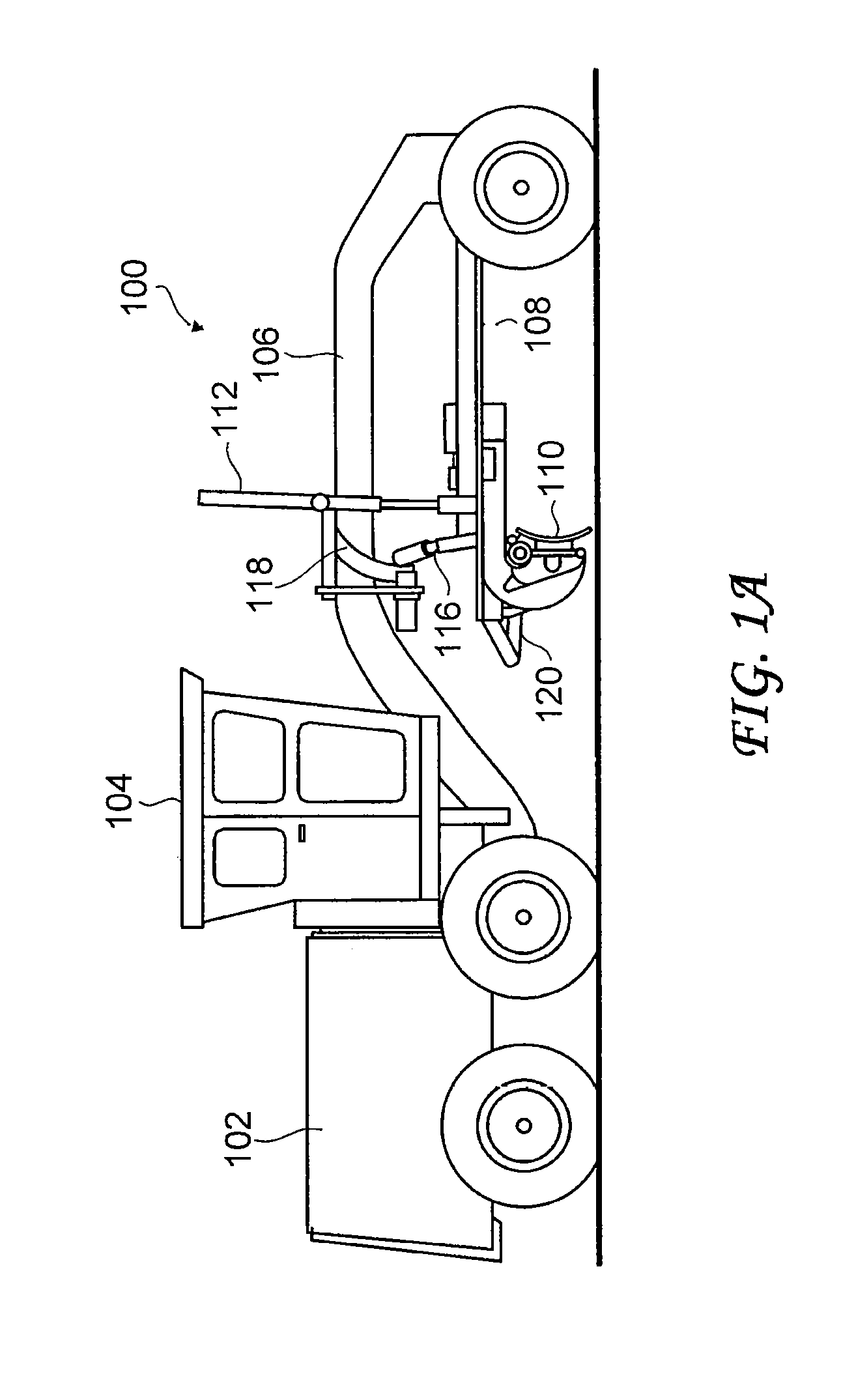
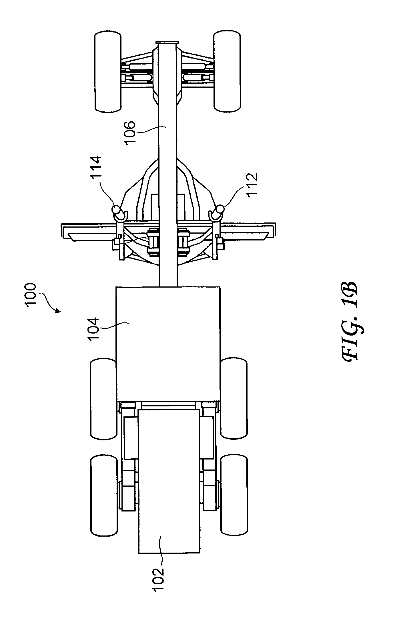
[0020]For a motor grader, primary blade parameters to be controlled are the blade slope angle and the blade elevation. FIG. 1A and FIG. 1B show a side view and a top view, respectively, of a motor grader 100. The motor grader 100 includes an engine 102, a cabin 104, and a front frame structure 106. The engine 102 is located at the rear of the motor grader 100, and the front frame ...


PUM


Abstract

The slope angle of a blade on an earthmoving machine is automatically controlled based on measurements from a three-axis gyroscope, a blade slope angle tilt sensor, and a blade tip angle tilt sensor mounted on the blade. A three-axis gyroscope has high dynamic response and high resistance to mechanical disturbances but is subject to potentially unbounded errors. A tilt sensor has bounded errors but has a slow dynamic response and a high sensitivity to mechanical disturbances. The combination of a three-axis gyroscope and two tilt sensors provides an advantageous measurement system. Algorithms for performing proper fusion of the measurements account for the lack of synchronization between the three-axis gyroscope and the tilt sensors and also screen out invalid measurements from the tilt sensors. The blade slope angle is controlled based on a reference blade slope angle and an estimate of the blade slope angle computed from properly fused measurements.

Description

[0001]This application claims the benefit of U.S. Provisional Application No. 61 / 453,256 filed Mar. 16, 2011, which is incorporated herein by reference.BACKGROUND OF THE INVENTION[0002]The present invention relates generally to earthmoving machines, and more particularly to automatic blade slope control.[0003]Construction machines referred to as earthmoving machines are used to shape a plot of land into a desired ground profile. Examples of earthmoving machines include bulldozers and motor graders. Bulldozers are used primarily for coarse movement of earth; motor graders are used primarily for fine control of the final ground profile. Bulldozers and motor graders are equipped with a blade to move earth. The blade position and blade attitude are adjustable. Blade position can be specified by parameters such as blade elevation and blade sideshift. Blade attitude can be specified by parameters such as blade tip angle and blade slope angle.[0004]Blade position and blade attitude are oft...

Claims


Application Information

Patent Timeline
Patent Type & Authority Patents(United States)
IPC IPC(8): E02F3/84
CPCE02F3/845E01C19/004
Inventor KONNO, HIROYUKIBRABEC, VERNON JOSEPHGRAHAM, RENARD TOMAS
Owner TOPCON POSITIONING SYST INC
Learn More