
Loop antenna with impedance matching

a technology of impedance matching and loop antenna, which is applied in the field of low-cost hdtv television antenna with impedance matching, can solve problems such as unbalanced rf, and achieve the effect of efficient coupling

Inactive Publication Date: 2014-05-27
RADIOSHACK ONLINE IPCO LLC +1
View PDF8 Cites 47 Cited by
  • Summary
  • Abstract
  • Description
  • Claims
  • Application Information

AI Technical Summary

Benefits of technology

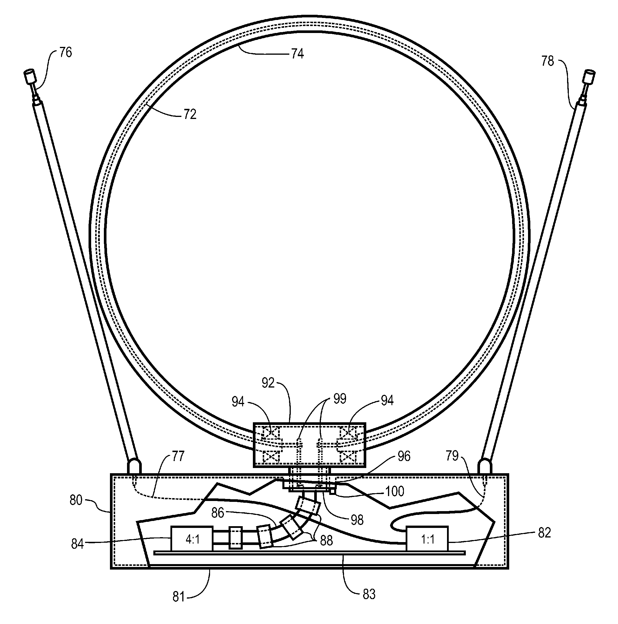
The present invention provides an improved antenna apparatus for receiving RF signals in the UHF and VHF bands. The apparatus includes a balun with a balanced RF input and an unbalanced RF output, which maintains a narrow range of impedances within the first band of frequencies as measured at the unbalanced RF output of the balun. The apparatus also includes a feed line with two electrical conductors that are aligned parallel and spaced apart a predetermined distance, which maintains efficient coupling of RF signals from the unbalanced RF output of the balun. The apparatus further includes a rotational stop to limit the rotation of the antenna element, a UHF band amplifier, a UHF band high pass filter, a UHF band low pass filter, a broadband radio frequency amplifier, and a power supply circuit with a direct current output. The technical effects of the invention include improved signal coupling, reduced twisting of the feed line, and efficient coupling of RF signals to the antenna.

Problems solved by technology

The apparatus has a balun with a balanced RF input and an unbalanced RF output.

Method used


Image

  • Loop antenna with impedance matching
  • Loop antenna with impedance matching
  • Loop antenna with impedance matching

Examples


Embodiment Construction

[0024]Illustrative embodiments and exemplary applications will now be described with reference to the accompanying drawings to disclose the advantageous teachings of the present invention.

[0025]While the present invention is described herein with reference to illustrative embodiments for particular applications, it should be understood that the invention is not limited thereto. Those having ordinary skill in the art and access to the teachings provided herein will recognize additional modifications, applications, and embodiments within the scope hereof and additional fields in which the present invention would be of significant utility.

[0026]In considering the detailed embodiments of the present invention, it will be observed that the present invention resides primarily in combinations of steps to accomplish various methods and components to form various apparatus. Accordingly, the apparatus components and method steps have been represented where appropriate by conventional symbols ...


PUM


Abstract

An antenna apparatus that has a base and an antenna element with a balanced RF output, which receives RF signals within a first band of frequencies. The apparatus includes a mount engaged with the base that rotatably supports the antenna about an axis of rotation. The apparatus has a balun with a balanced RF input and an unbalanced RF output. A feed line is coupled between the balanced RF output and the balanced RF input. The feed line includes two electrical conductors that have a predetermined length and that are aligned substantially in parallel, and supportively spaced apart a predetermined distance by plural insulators. The feed line is further arranged to maintain the predetermined distance between the two electrical conductors as the antenna element rotates with respect to the base. The predetermined length and the predetermined distance are selected to yield a narrow range of impedances within the first band of frequencies as measured at the unbalanced RF output of the balun, which enables efficient coupling of the RF signals from the unbalanced RF output of the balun.

Description

BACKGROUND OF THE INVENTION[0001]1. Field of the Invention[0002]The present invention relates to radio frequency antennas. More particularly, the present invention relates to low cost HDTV television antenna with impedance matching for a loop element.[0003]2. Description of the Related Art[0004]Prior art television antennas fall into two general categories, the indoor antenna and the outdoor antenna. Indoor antennas are sometimes referred to as set-top antenna, and outdoor antennas are commonly mounted to a mast located above the rooftop of a home or other building. Since US television broadcasts have occurred on both the VHF band (54 MHz to 216 MHz) and the UHF band (470 MHz to 890 MHz), prior art antenna structures have been designed to receive in both of these bands. In fact, most prior art antenna systems have included two antenna structures, one for each band. For example, a common type prior art indoor antenna includes a 7.5″ loop antenna for the UHF band and a pair of telesco...

Claims


Application Information

Patent Timeline
IPC IPC(8): H01Q21/00H01Q3/00H01Q9/16
CPCH01Q9/30H01P5/10H01Q3/08H01Q7/00H01Q1/10H01Q9/16H01Q21/00H01Q9/14H01Q3/00
Inventor LAM, ALAN, MAN, LUNG
Owner RADIOSHACK ONLINE IPCO LLC
Learn More