
Light emitting device having plural light-emitting sections with resin walls within resin frame

a light-emitting device and resin-frame technology, applied in the direction of solid-state devices, lighting and heating devices, lighting support devices, etc., can solve the problems of difficult to optimize a white light spectrum, difficult to achieve a high color rendering property, and inability to observe illuminated objects naturally in some cases, etc., to achieve excellent color mixing properties, increase integration, and high color rendering properties

Inactive Publication Date: 2014-05-27
SHARP KK
View PDF20 Cites 28 Cited by
  • Summary
  • Abstract
  • Description
  • Claims
  • Application Information

AI Technical Summary

Benefits of technology

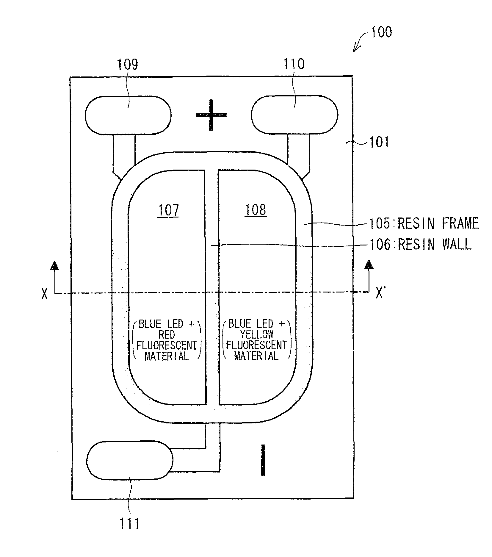
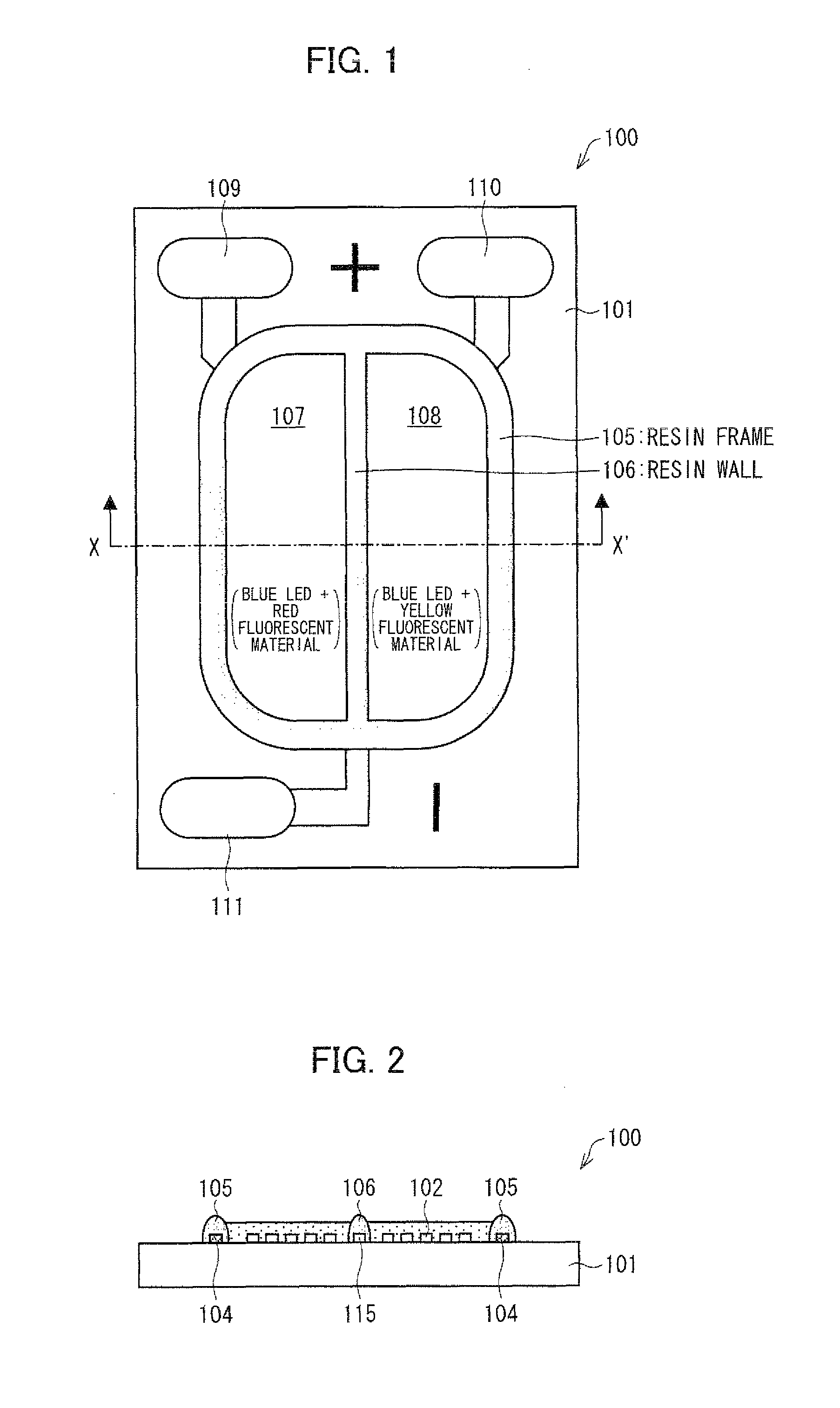
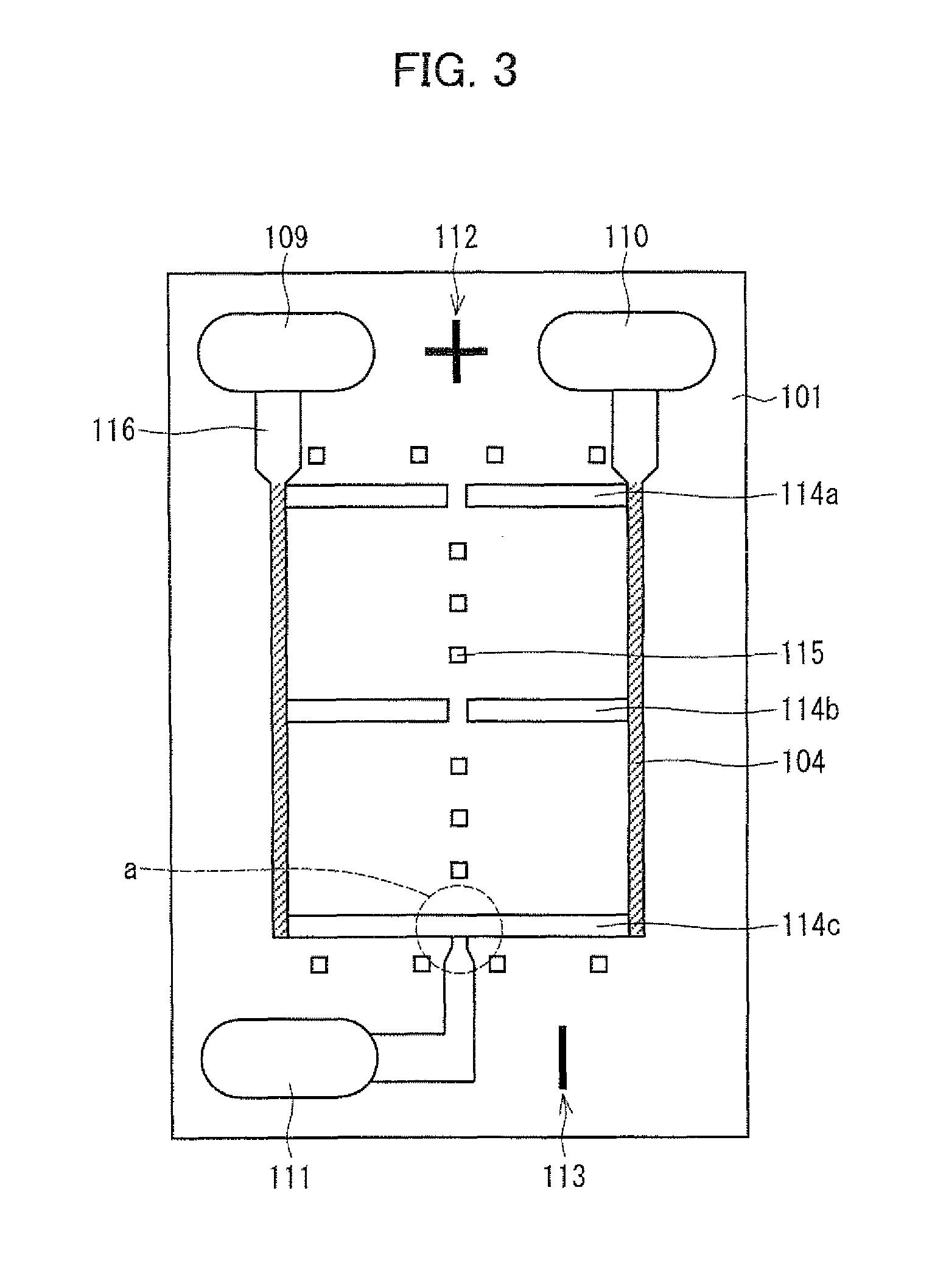
[0028]As described above, a light emitting device of the present invention is a light emitting device using light emitting elements, and includes: a substrate; a resin frame provided annularly on the substrate; a resin wall provided on the substrate so as to partition an area surrounded by the resin frame into n (2≦n) zones; light-emitting sections provided in the respective zones, each of which light-emitting sections includes at least one light emitting element; and anode electrodes and a cathode electrode provided so that each of the light-emitting sections receives current via a corresponding anode electrode and the cathode electrode, at least two of the light-emitting sections emitting respective pieces of light each having at least one color, which respective pieces of light having different colors from each other, the anode electrodes including k (2≦k≦n) anode electrodes provided outside the resin frame on the substrate in such a manner that each of the anode electrodes is electrically connected to at least one of the light-emitting sections such that the anode electrodes are electrically connected to different light-emitting sections.
[0029]With the arrangement, it is possible to increase an integration degree, to achieve a high color rendering property and an excellent color mixing property, and to easily adjust a chromaticity so that light can be easily generated at an intended chromaticity.
[0030]An illumination device according to the present invention includes the above light emitting device as a light source.
[0031]This makes it possible to produce a very excellent illumination device. Further, since the light emitting device uses a light emitting element, it is possible to save energy and space, and further the illumination device can be used for long periods.

Problems solved by technology

This makes it difficult to optimize a white light spectrum.
Further, in such a technique as disclosed in Patent Literature 2 that causes three types of LED elements to be simultaneously turned on, even if it seems, to the eyes, that white light is obtained, an illuminated object cannot be observed naturally in some cases.
In view of this, it is difficult to achieve a high color rendering property by the techniques disclosed in Patent Literature 1 and 2.
However, in the technique disclosed in Patent Literature 3, the color rendering property is still low because the blue light, emitted from the blue LED element, is reabsorbed by the red LED element and the green LED element.
For this reason, it is impossible to achieve a high color rendering property by use of the method.
However, several methods have been developed to compensate such a red-light emission component that tends to be insufficient.

Method used


Image

  • Light emitting device having plural light-emitting sections with resin walls within resin frame
  • Light emitting device having plural light-emitting sections with resin walls within resin frame
  • Light emitting device having plural light-emitting sections with resin walls within resin frame

Examples


embodiment 2

[0137]FIG. 9 is a top view illustrating one exemplary arrangement of a light emitting device 200 in accordance with the present embodiment. FIG. 10 is a top view of the light emitting device 200 in which LED chips 102 are provided.

[0138]The light emitting device 200 according to the present embodiment is different from the light emitting device 100 according to Embodiment 1 in that three fluorescent-material-containing resin layers are provided, and they are arranged in a different manner from Embodiment 1. Except for that, the light emitting device 200 has an equivalent arrangement to that of the light emitting device 100 according to Embodiment 1.

[0139]As illustrated in FIG. 9 and FIG. 10, the light emitting device 200 according to the present embodiment includes a substrate 101, LED chips 102, printed resistors 104, a resin frame 105, resin walls 106, a third fluorescent-material-containing resin layer 201 (green-fluorescent-material-containing resin layer), a fourth fluorescent-...

embodiment 3

[0157]FIG. 11 is a top view illustrating one exemplary arrangement of a light emitting device 300 in accordance with the present embodiment.

[0158]The light emitting device 300 according to the present embodiment is different from the light emitting device 100 according to Embodiment 1 in that four fluorescent-material-containing resin layers are provided, and they are arranged in a different manner from Embodiment 1. Except for that, the light emitting device 300 according to the present embodiment has an equivalent arrangement to that of the light emitting device 100 according to Embodiment 1.

[0159]As illustrated in FIG. 11, the light emitting device 300 according to the present embodiment includes a substrate 101, LED chips 102, printed resistors 104, a resin frame 105, a resin wall 106, a sixth fluorescent-material-containing resin layer 301 (red-fluorescent-material-containing resin layer), a seventh fluorescent-material-containing resin layer 302 (yellow-fluorescent-material-co...

embodiment 4

[0174]FIG. 12 is a top view illustrating one exemplary arrangement of a light emitting device 400 in accordance with the present embodiment.

[0175]The light emitting device 400 according to the present embodiment is different from the light emitting device 300 according to Embodiment 3 in the number of anode electrodes and by which anode electrode each of the light-emitting sections are driven. Further, the light emitting device 400 according to Embodiment 4 is different from the light emitting device 300 according to Embodiment 3 in that a red fluorescent material (Sr.Ca)AlSiN3:Eu is used as the sixth particulate fluorescent material and the ninth particulate fluorescent material. Except for that, the light emitting device 400 according to the present embodiment has an equivalent arrangement to that of the light emitting device 300 according to Embodiment 3.

[0176]Note that by using the red fluorescent material (Sr.Ca)AlSiN3:Eu instead of the red fluorescent material CaAlSiN3:Eu, red...


PUM


Abstract

A light emitting device is a light emitting device using light emitting elements and includes: a substrate; a resin frame provided circularly on the substrate; a resin wall provided on the substrate so as to partition an area surrounded by the resin frame into 2 zones; light-emitting sections (a first light-emitting section: blue LEDs+red fluorescent material, a second light-emitting section: blue LEDs+yellow fluorescent material) provided in the respective zones, each of which light-emitting sections includes at least one light emitting element; and first and second anode electrodes and a cathode electrode provided so that each of the light-emitting sections receives current via a corresponding anode electrode and the cathode electrode, the light-emitting sections emitting respective pieces of light each having at least one color, which respective pieces of light have different colors from each other, the first and second anode electrodes being electrically connected to the first and second light-emitting sections, respectively. With the arrangement, which can increase an integration degree, it is possible to achieve a high color rendering property and an excellent color mixing property, to easily adjust a chromaticity, and to easily generate light with a desired chromaticity.

Description

[0001]This Nonprovisional application claims priority under 35 U.S.C. §119(a) on Patent Applications No. 2010-113477 filed in Japan on May 17, 2010, and No. 2010-164169 filed in Japan on Jul. 21, 2010, the entire contents of which are hereby incorporated by reference.TECHNICAL FIELD[0002]The present invention relates to a light emitting device and an illumination device, each of which employs an LED (Light Emitting Diode). The present invention particularly relates to a technique of generating white light with an excellent color rendering property and an excellent color mixing property.BACKGROUND ART[0003]In recent years, use of an LED in light sources, such as a general illumination light source and a light source of a backlight for a TV, is been rapidly promoted, as one of environmental countermeasures against global warming. Such light sources employ LED illumination modules configured to emit white light. How to generate white light by use of an LED can be exemplified by, for ex...

Claims


Application Information

Patent Timeline
Patent Type & Authority Patents(United States)
IPC IPC(8): F21V9/16H01L33/00F21S4/00F21V21/00H01L29/20H01L29/18
CPCH01L25/0753H01L2924/3025H01L33/62H01L2224/48137H01L33/504H01L2924/00
Inventor AGATANI, MAKOTOHATA, TOSHIONADA, TOMOKAZUUEMURA, TOYONORIISHIZAKI, SHINYA
Owner SHARP KK
Learn More