
Correction of spectral differences in a multi-display system

a multi-display system and correction technology, applied in the field of multi-display systems, can solve the problems of multi-display systems not configured to adjust luminance and chromaticity of the screen, giving a feeling of unease to the observer, and reducing the efficiency of multi-display systems, so as to reduce the difficulty of adjusting luminance and chromaticity between adjacent image display devices, simplify the device configuration, and eliminate luminance shift and chromaticity shift. the effect o

Active Publication Date: 2014-11-11
SHARP KK
View PDF11 Cites 1 Cited by
  • Summary
  • Abstract
  • Description
  • Claims
  • Application Information

AI Technical Summary

Benefits of technology

The technology aims to create a multi-display system that can overcome the issue of variations in brightness and color between different display devices, which can occur over time without stopping the system's operation.

Problems solved by technology

When a multi-display system is put into practical use, there is a problem in that a luminance shift and a chromaticity shift occur between the respective adjacent image display devices due to individual differences between the respective adjacent image display devices and changes over time occurring individually.
When a luminance shift and a chromaticity shift occur between the respective image display devices, there is a problem in that the displayed image appears unnatural to an observer, thus giving a feeling of unease to the observer.
However, the multi-display system is not configured to adjust luminance and chromaticity of the screen of each display panel while focusing on the individual differences between the respective image display devices and the temporal change of the individual image display device.
The adjustment operation using such a dedicated adjustment device incurs a lot of time and labor.
In addition, there is a problem in that in order to execute adjustment using such a dedicated adjustment device, it is necessary to execute the adjustment operation after the operation of the multi-display system is halted once.
When the spectral characteristics detector is provided in each display region, individual differences between the plural sensors, and an operational delay and a control delay due to sensing and analog / digital (A / D) conversion may occur.

Method used


Image

  • Correction of spectral differences in a multi-display system
  • Correction of spectral differences in a multi-display system
  • Correction of spectral differences in a multi-display system

Examples


Embodiment Construction

[0060]Now referring to the drawings, preferred embodiments are described below.

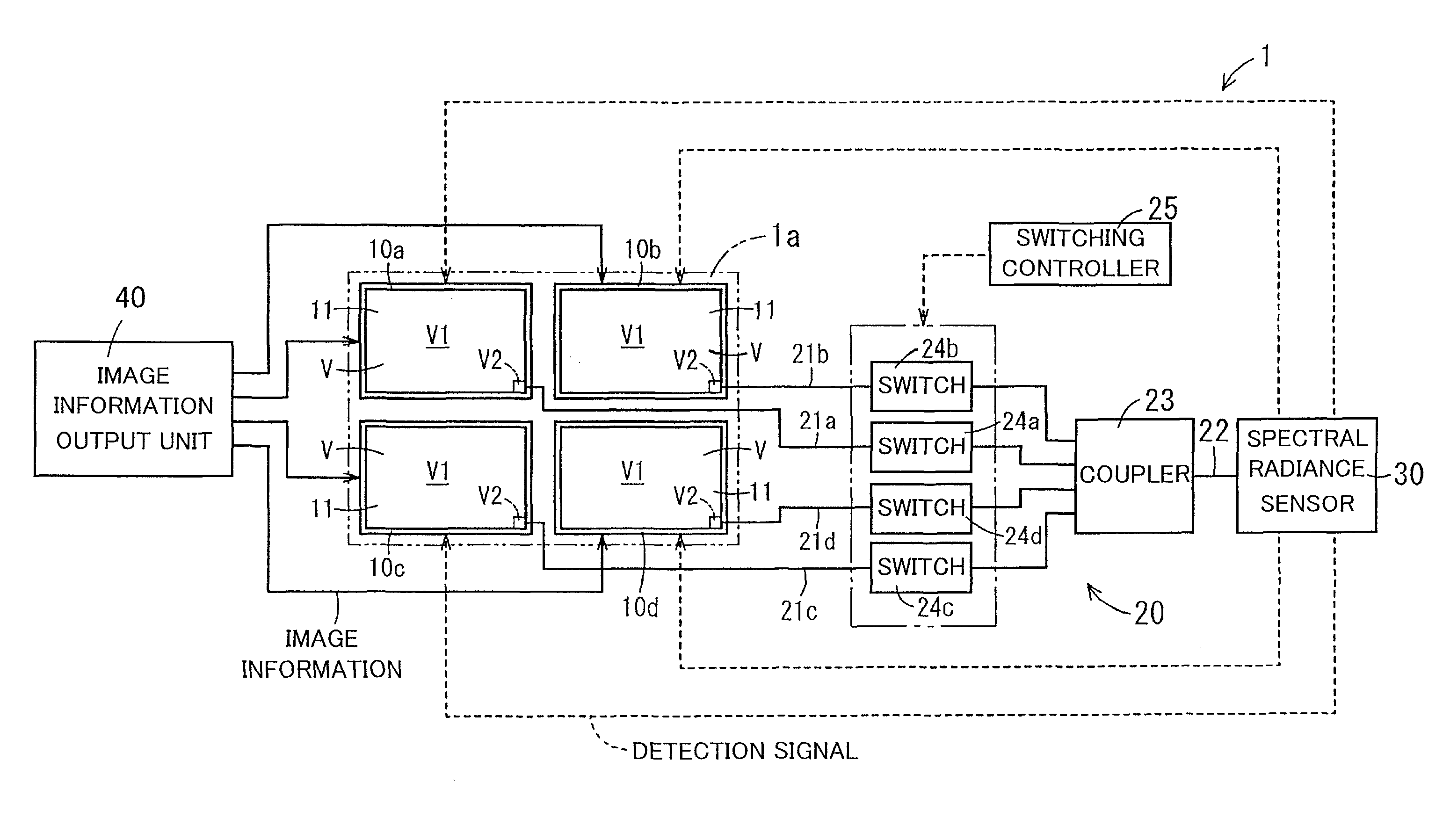
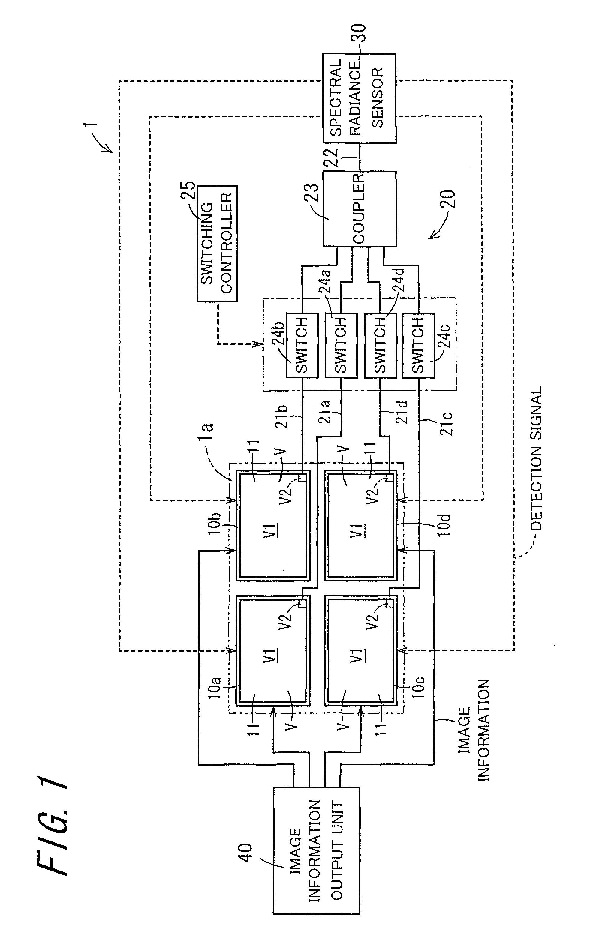
[0061]FIG. 1 is a system diagram schematically showing a multi-display system 1 according to one embodiment. The multi-display system 1 comprises four image display devices 10a to 10d, an optical transmitting unit 20, a single spectral radiance sensor 30, and an image information output unit 40.

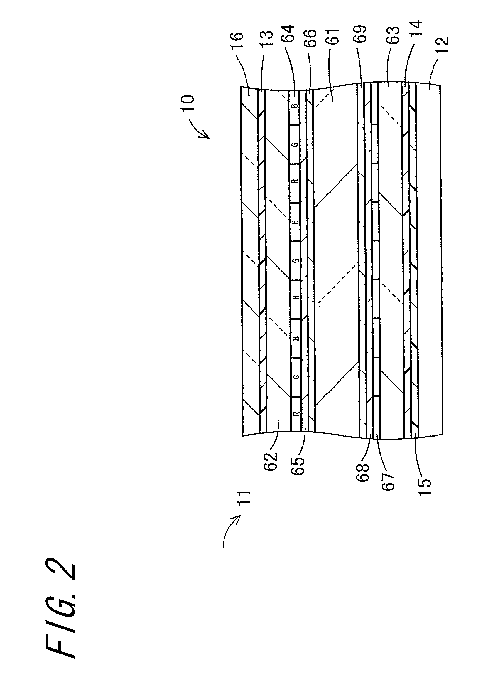
[0062]The respective image display devices 10a to 10d include liquid crystal display (abbreviated as LCD) modules 11 having the same screen size. The multi-display system 1 is configured by arranging four image display devices 10a to 10d close to each other in a 2-by-2 matrix.

[0063]A multi-display screen 1a is formed by the screens of the image display devices 10a, 10b, 10c, and 10d which are located top-left, top-right, bottom-left, and bottom-right as viewed from a front side. The multi-display screen 1a has a screen size twice that of the single image display device 10a in both the vertical and horizontal direct...


PUM


Abstract

A multi-display system includes a test pattern display controller that causes a test pattern to be displayed in a predetermined display region on a periphery of an LCD module of each image display device, an optical transmitting unit that constitutes a plurality of transmission channels each capable of transmitting an emitted light from each of the display regions, a spectral radiance sensor that detects spectral characteristics of the emitted light transmitted by each of the transmission channels, and an adjustment unit that adjusts, based on the spectral characteristics detected by the spectral radiance sensor, luminance and chromaticity of the image display device having the LCD module that has outputted the emitted light having the spectral characteristics so that the difference from luminance and chromaticity of the adjacent image display devices decreases.

Description

CROSS-REFERENCE TO RELATED APPLICATION[0001]This application claims priority to Japanese Patent Application No. 2010-175817, which was filed on Aug. 4, 2010, the contents of which are incorporated herein by reference in its entirety.BACKGROUND OF THE TECHNOLOGY[0002]1. Field of the Technology[0003]The technology relates to a multi-display system capable of adjusting luminance and chromaticity of a plurality of image display devices constituting a multi-display screen to thereby eliminate a luminance shift and a chromaticity shift between the respective adjacent image display devices.[0004]2. Description of the Related Art[0005]In recent years, a so-called “multi-display system” is being practically used in which a large display screen (hereinafter referred to as a “multi-display screen”) is formed by the entirety of a plurality of image display devices by arranging the plurality of image display devices having a display panel capable of displaying image information close to each oth...

Claims


Application Information

Patent Timeline
Patent Type & Authority Patents(United States)
IPC IPC(8): G09G5/00G09G5/10G09G5/02G06F3/14
CPCG09G2320/0233G09G2360/145G06F3/1431
Inventor SUGIYAMA, KOICHI
Owner SHARP KK
Learn More