
Compact double-contact secured pushbutton switch

a pushbutton switch and double-contact technology, applied in the field of compact double-contact secured pushbutton switch, can solve the problems of affecting the manufacture cost, affecting the reliability of the switch, so as to achieve the effect of improving reliability, dependability and a lifetim

Inactive Publication Date: 2014-05-27
THALES SA
View PDF11 Cites 8 Cited by
  • Summary
  • Abstract
  • Description
  • Claims
  • Application Information

AI Technical Summary

Benefits of technology

The invention is a pushbutton switch that has a low cost and offers improved reliability and durability. The switch has a plunger that triggers the depression of an upper dome positioned above switching means. The depression of the upper dome results in the depression of the switching means, creating a first and second electric circuit. The switch also has a flexible metal platelet or an upper dome with greater force required to depress it compared to the lower dome.

Problems solved by technology

A drawback associated with this technical solution lies in the fact that producing such a switch is difficult, in as much as the two electric contacts have to be activated simultaneously.
The simultaneous activation of the two electric contacts is all the more difficult when the pushbutton of the switch is pressed on the edges or else on the crest thereof.
It is possible to overcome this drawback by equipping the switch with accurate guiding devices, but to the detriment of the cost of manufacture and to the price of spurious friction effects detrimental to the comfort of the user.
Furthermore, the guiding systems may lead to problems caused by the switch becoming jammed, due, for example, to bracing effects.

Method used


Image

  • Compact double-contact secured pushbutton switch
  • Compact double-contact secured pushbutton switch
  • Compact double-contact secured pushbutton switch

Examples


Embodiment Construction

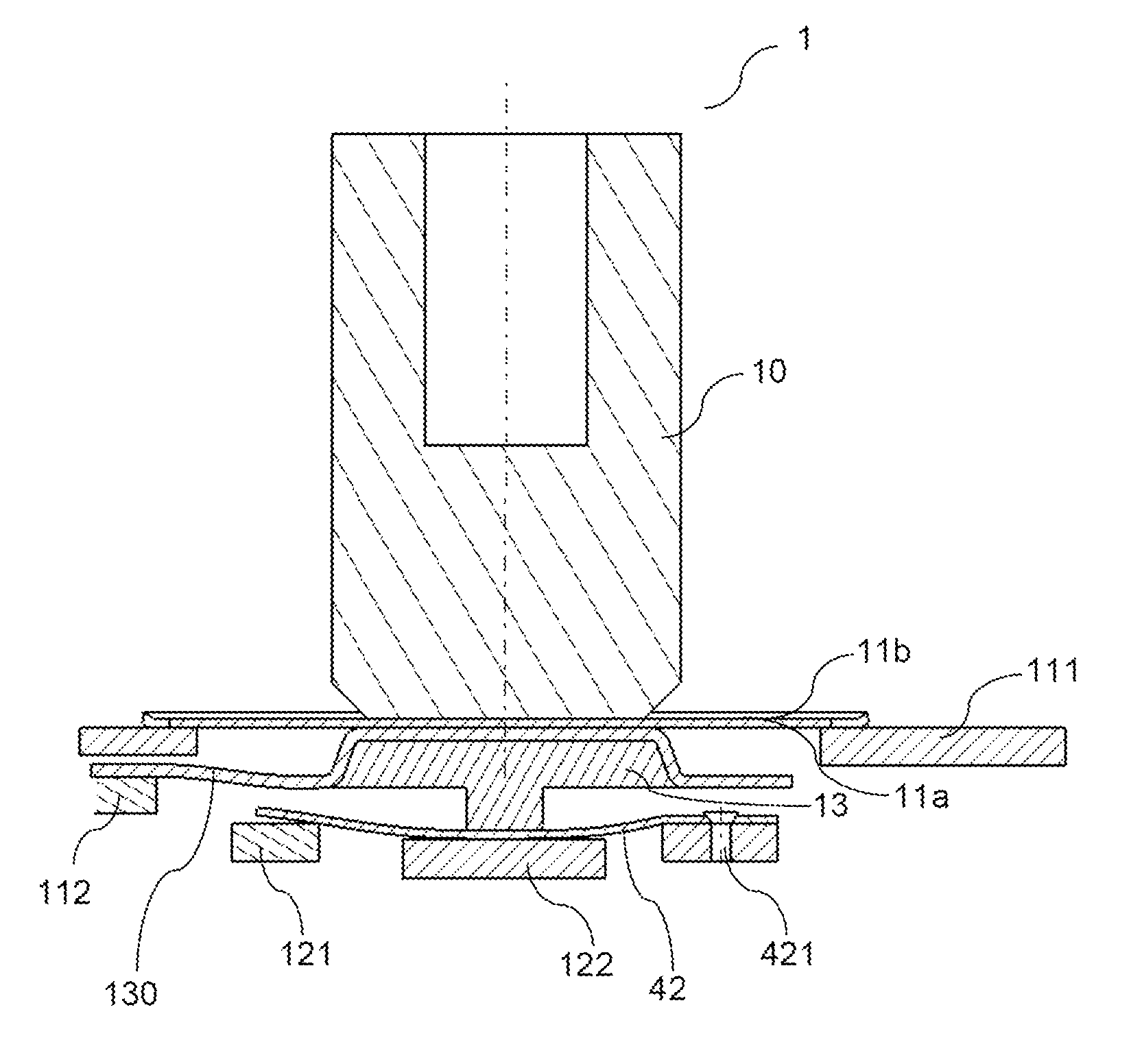
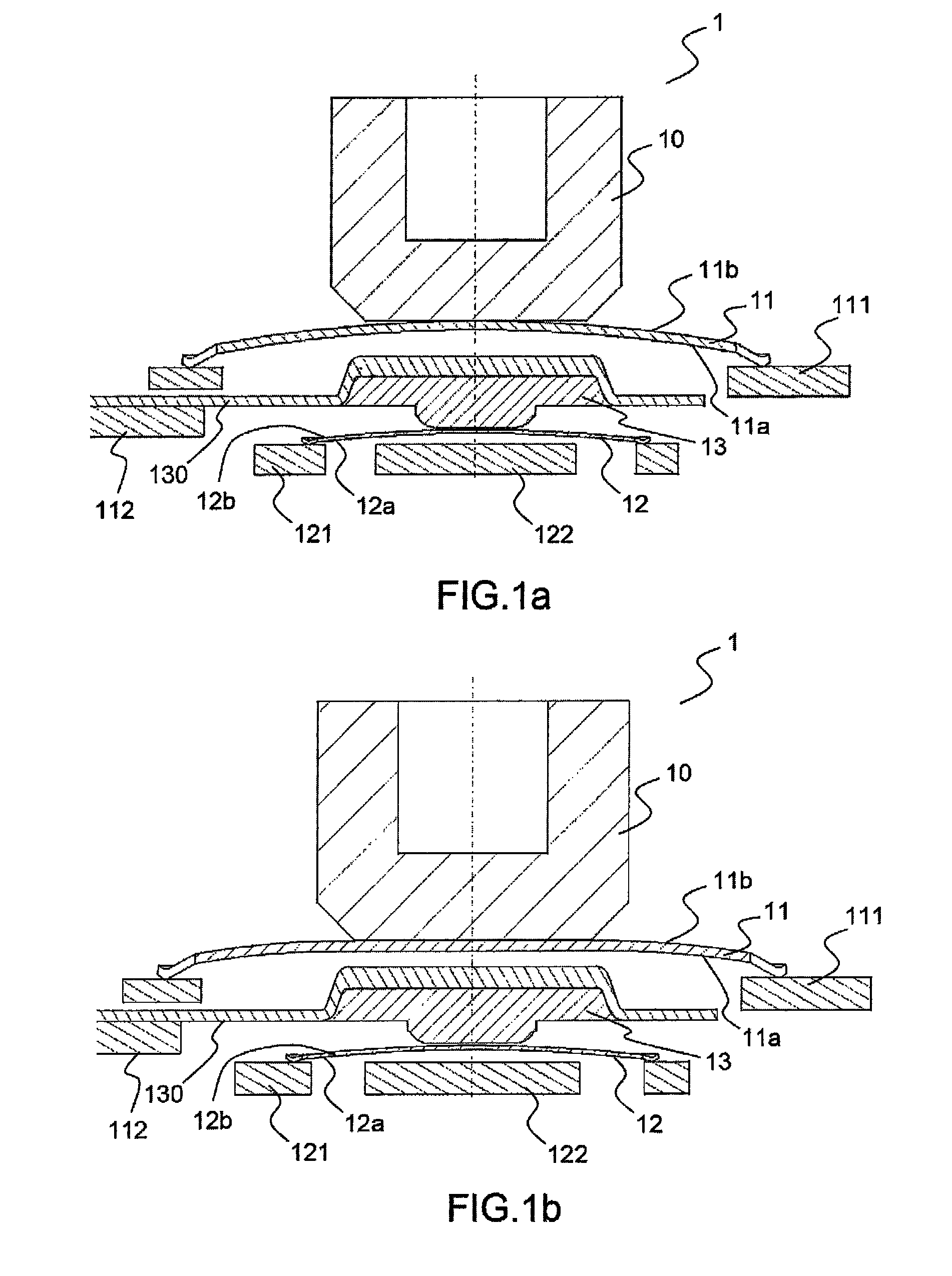
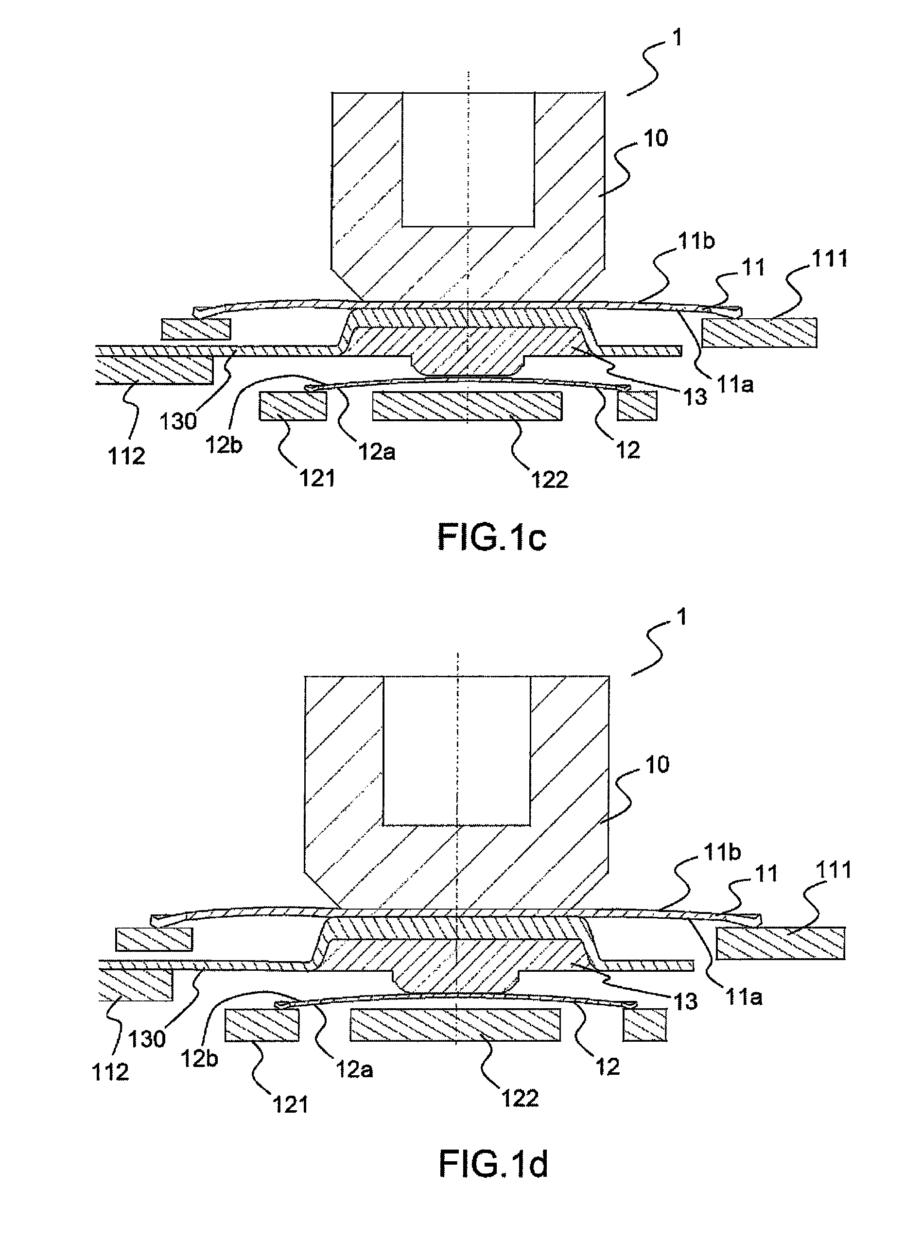
[0026]Referring to FIG. 1a, a pushbutton switch 1 may comprise, in an exemplary embodiment, an actuator or “plunger”10. The plunger 10 is positioned above the crest of an upper dome 11 produced in an electrically conductive material. Switching means, for example formed by a lower dome 12, are positioned below the upper dome 11. The upper dome 11 notably comprises a bottom surface 11a and a top surface 11b. Similarly, the lower dome 12 comprises a bottom surface 12a and a top surface 12b.

[0027]Advantageously, the diameter of the upper dome 11 is chosen to be greater than the diameter of the lower dome 12. According to a specific feature of the present invention, the depression of the upper dome 11 should systematically result in the depression of the lower dome 12, so that one and the same activation force exerted by the user on the plunger 10 will allow for the depression of both domes 11, 12. Thus, the force required to depress the upper dome 11 is greater than the force required ...


PUM


Abstract

A pushbutton switch comprises a plunger, which provokes, under the action of pressure by a user, the depression of an upper dome positioned above switching means, any depression of the upper dome necessarily provoking the depression of the switching means, the crest of the upper dome and the switching means having a down position, a first electric contact being produced between a primary contact and a secondary contact of the upper dome forming a first electric circuit when the crest of the upper dome is in the down position, and a second electric contact being produced between a primary contact and a secondary contact of the switching means forming a second electric circuit when the switching means are in the down position.

Description

CROSS-REFERENCE TO RELATED APPLICATION[0001]This application claims priority to foreign French patent application No. FR 1004818, filed on Dec. 10, 2010, the disclosure of which is incorporated by reference in its entirety.FIELD OF THE INVENTION[0002]The present invention relates to a compact double-contact secured pushbutton switch. It applies notably to the field of electric switches with a single-function pushbutton, or a redundant or secured function, intended to initiate critical functions, used for example in the aeronautical field.BACKGROUND[0003]The electric switches intended to initiate critical functions, used for example on aircraft instrument panels, must satisfy a certain number of constraints. Notably, certain functions require their operation to be effected via pressure on a switch that is redundant from an electrical point of view, that is to say, a switch that simultaneously establishes the electric contact for at least two electric circuits implementing, for exampl...

Claims


Application Information

Patent Timeline
Patent Type & Authority Patents(United States)
IPC IPC(8): H01H13/14H01H13/88H01H9/00H01H13/702
CPCH01H2225/018H01H13/702H01H13/14H01H13/88H01H13/64H01H2221/026H01H2203/038H01H13/66H01H13/803H01H13/807H01H2001/0005H01H2225/002H01H2225/008H01H13/26
Inventor BIGAND, JEAN-LOUIS
Owner THALES SA
Learn More