Dispenser of product
a technology of dispensers and products, applied in the field of dispensers of products, can solve the problems of unsatisfactory control of the position of use of known dispensers, and achieve the effects of improving the control of the position of use, simplifying assembly, and improving the visibility of the mirror
- Summary
- Abstract
- Description
- Claims
- Application Information
AI Technical Summary
Benefits of technology
Problems solved by technology
Method used
Image
Examples
first embodiment
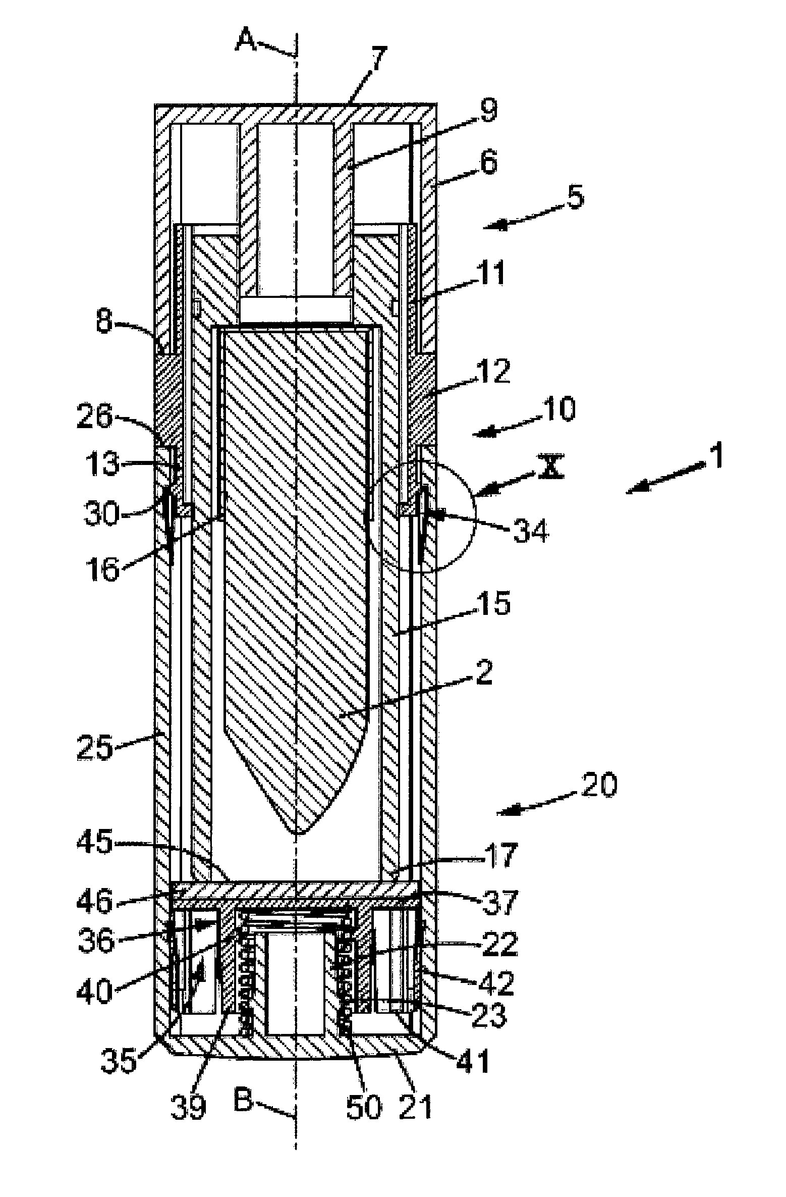
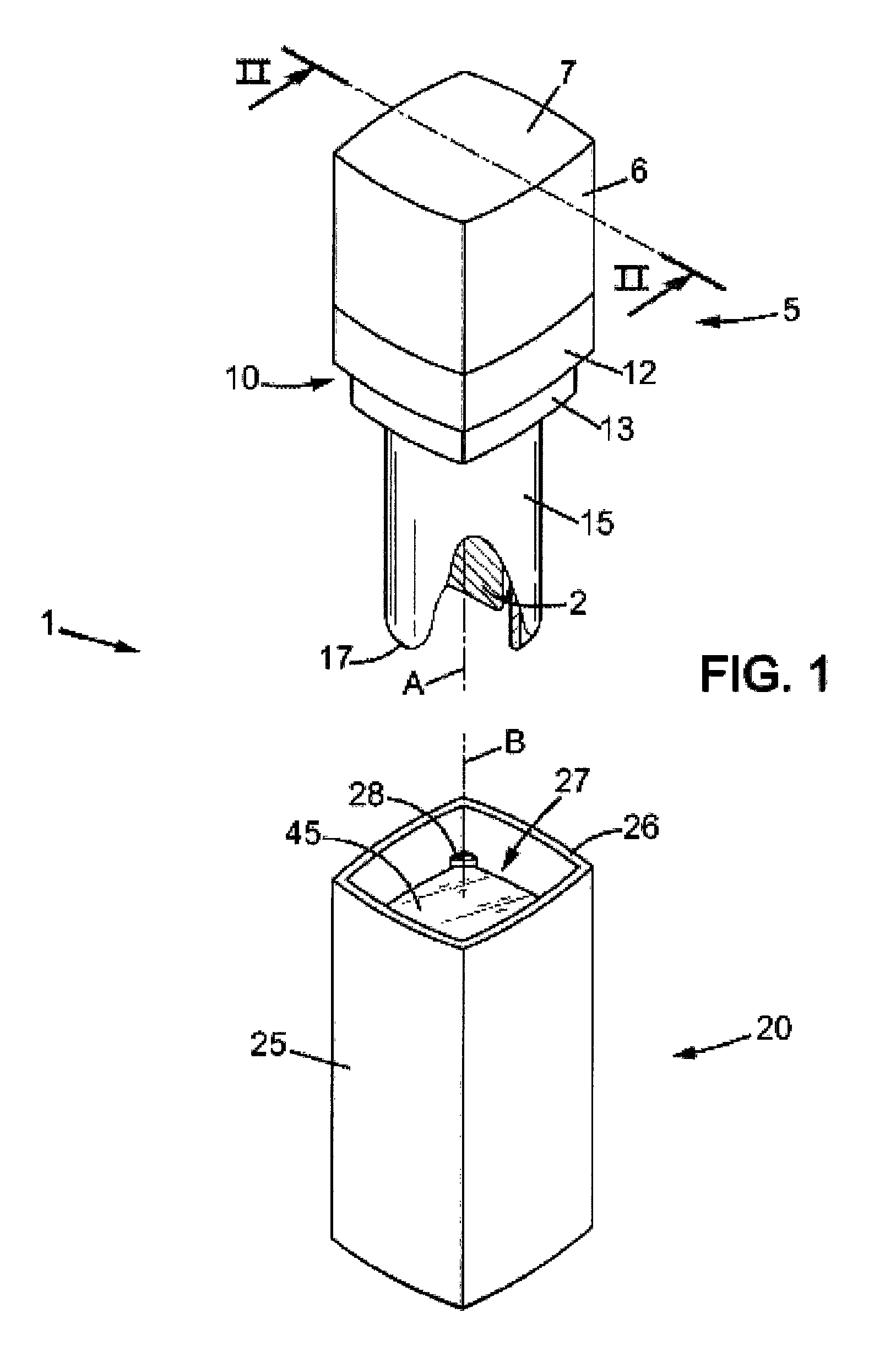
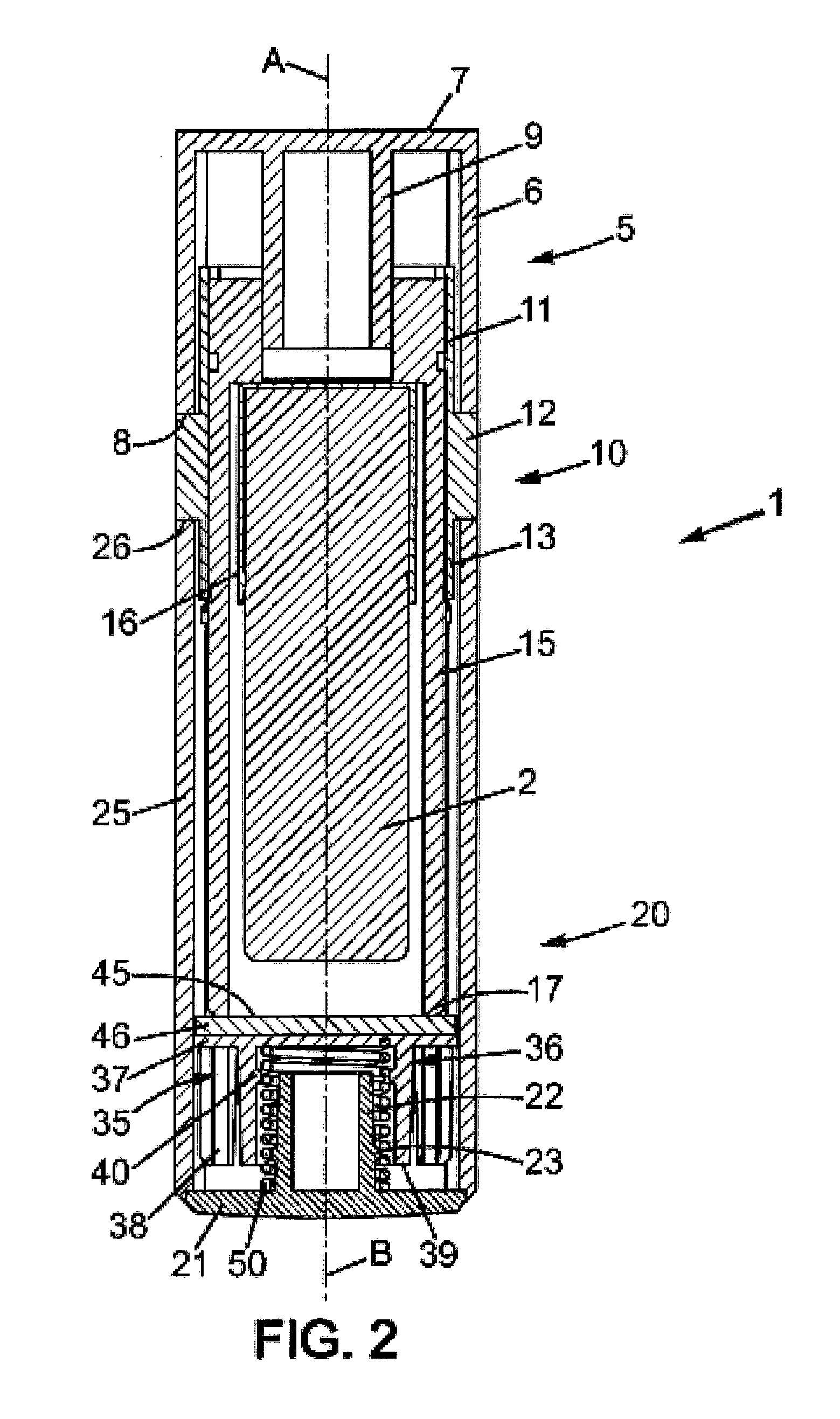
[0053]In a first embodiment, shown in FIGS. 1 and 2, the applicator device extends along an axis A and comprises a base 5, a sheath 15 mounted on the base 5 and a cup 16, also known as a shell, mounted on the sheath 15.
[0054]The base 5 has a tubular side wall 6 with a rectangular cross-section extending from a rectangular transverse wall 7 to a free edge 8. The side wall 6 surrounds a tubular sleeve 9 centred on the axis A of the applicator device and extending from the transverse wall 7.
[0055]In the embodiment shown, the applicator device comprises a tubular ferrule 10 having a central portion 12 that tops the free edge 8 of the base 5 so that the outer surface of the central portion 12 is flush with the outer surface of the base 5. In particular, the ferrule 10 comprises two narrow portions 11, 13 arranged on either side of the central portion 12 relative to the axis A of the applicator device. One of the narrow portions 11 is fitted into the base 5, the other narrow portion 13 fo...
second embodiment
[0077]the lipstick is described with reference to FIGS. 5 to 10.
[0078]As for the first embodiment, the lipstick according to the second embodiment comprises the applicator device described above together with a case 20 and a mobile member 35 similar to those described above.
[0079]However, the second embodiment differs from the first embodiment mainly in the form taken by the abutment surface 30 with which the mobile member 35 is in contact in the position of use.
[0080]In the second embodiment, the support 36 shown in FIG. 7 comprises two base walls 41 that extend perpendicularly from two opposite sides of the plate 37. Two elastically deformable tabs 42 are formed on the base walls 41 by cut-outs in the base walls 41. The tabs 42 extend generally perpendicular to the plate 37 to a free end near the plate 37. The tabs 42 are elbowed so that the free ends are pointing outwards away from the rest of the base walls 41.
[0081]Once the support 36 has been placed in the housing 27, as shown...
third embodiment
[0088]the lipstick is shown in FIGS. 11 and 12.
[0089]The lipstick according to the third embodiment comprises the applicator device and the case 20 described above in relation to the second embodiment, together with a mobile member 35 similar to that described above in relation to the second embodiment.
[0090]In particular, as shown in FIG. 12, the support 36 of the lipstick according to the third embodiment comprises one or more tabs 42 in contact with the inner surface of the side wall 25 of the case to guide its movement and abut against the stop surface 30 of one or more recesses 34 made in the side wall 25 in the position of use.
[0091]The lipstick according to the third embodiment differs from the lipstick according to the second embodiment mainly in the form of the support 36 and the arrangement of the mirror 46.
[0092]The support 36 comprises a tubular side wall 43 with a rectangular cross-section that extends along the central axis B from the transverse plate 37. The side wall...
PUM
 Abstract
Description
Claims
Application Information
 - R&D
- Intellectual Property
- Life Sciences
- Materials
- Tech Scout
- Unparalleled Data Quality
- Higher Quality Content
- 60% Fewer Hallucinations
Browse by: Latest US Patents, China's latest patents, Technical Efficacy Thesaurus, Application Domain, Technology Topic, Popular Technical Reports.
© 2025 PatSnap. All rights reserved.Legal|Privacy policy|Modern Slavery Act Transparency Statement|Sitemap|About US| Contact US: help@patsnap.com


