
Display device

a display device and display technology, applied in the field of display devices, can solve problems such as measurement errors, quantity of light incident, and measurement errors

Active Publication Date: 2014-05-27
SAMSUNG DISPLAY CO LTD
View PDF9 Cites 0 Cited by
  • Summary
  • Abstract
  • Description
  • Claims
  • Application Information

AI Technical Summary

Benefits of technology

[0009]Embodiments of the present invention provide a display device that can precisely control a light source by measuring the quantity of light from the light source under uniform conditions.
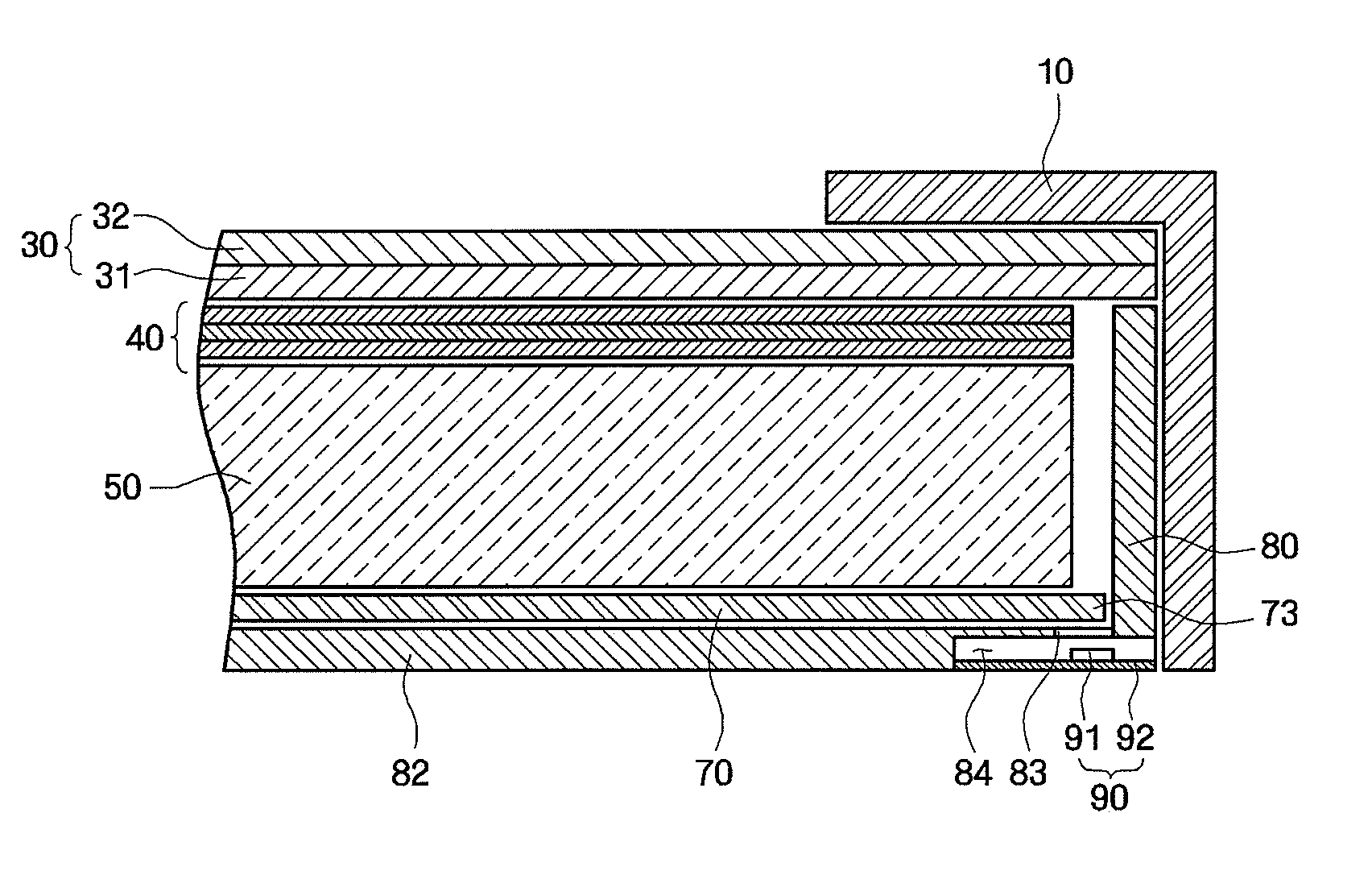
[0010]A display device, according to an embodiment of the present invention, includes a display panel displaying an image, a light source generating light, a light guide plate guiding and providing the light to the display panel, a receptacle accommodating the light source and the light guide plate, an optical sensor fixed to the receptacle to sense the light, a light receiving hole formed in the receptacle to provide a path through which the light reaches the optical sensor; and an optical adjustment member interposed between the light guide plate and the optical sensor to reduce luminance of the light incident to the optical sensor; wherein the optical sensor is completely exposed to the optical adjustment member through the light receiving hole.

Problems solved by technology

However, if external conditions of the display device are changed, the measurement conditions of the optical sensor are also changed, and an error may occur in the measured value.
The change in the relative position between the constituent element, such as the light receiving hole, and the optical sensor causes a difference in the quantity of light incident to the optical sensor, and thus a measurement error may occur.

Method used


Image

  • Display device
  • Display device
  • Display device

Examples


Embodiment Construction

[0027]Hereinafter, exemplary embodiments of the present invention will be described in more detail with reference to the accompanying drawings. However, the present invention may be embodied in many different forms and should not be construed as being limited to the embodiments disclosed herein. The same drawing reference numerals may be used for the same elements across various figures.

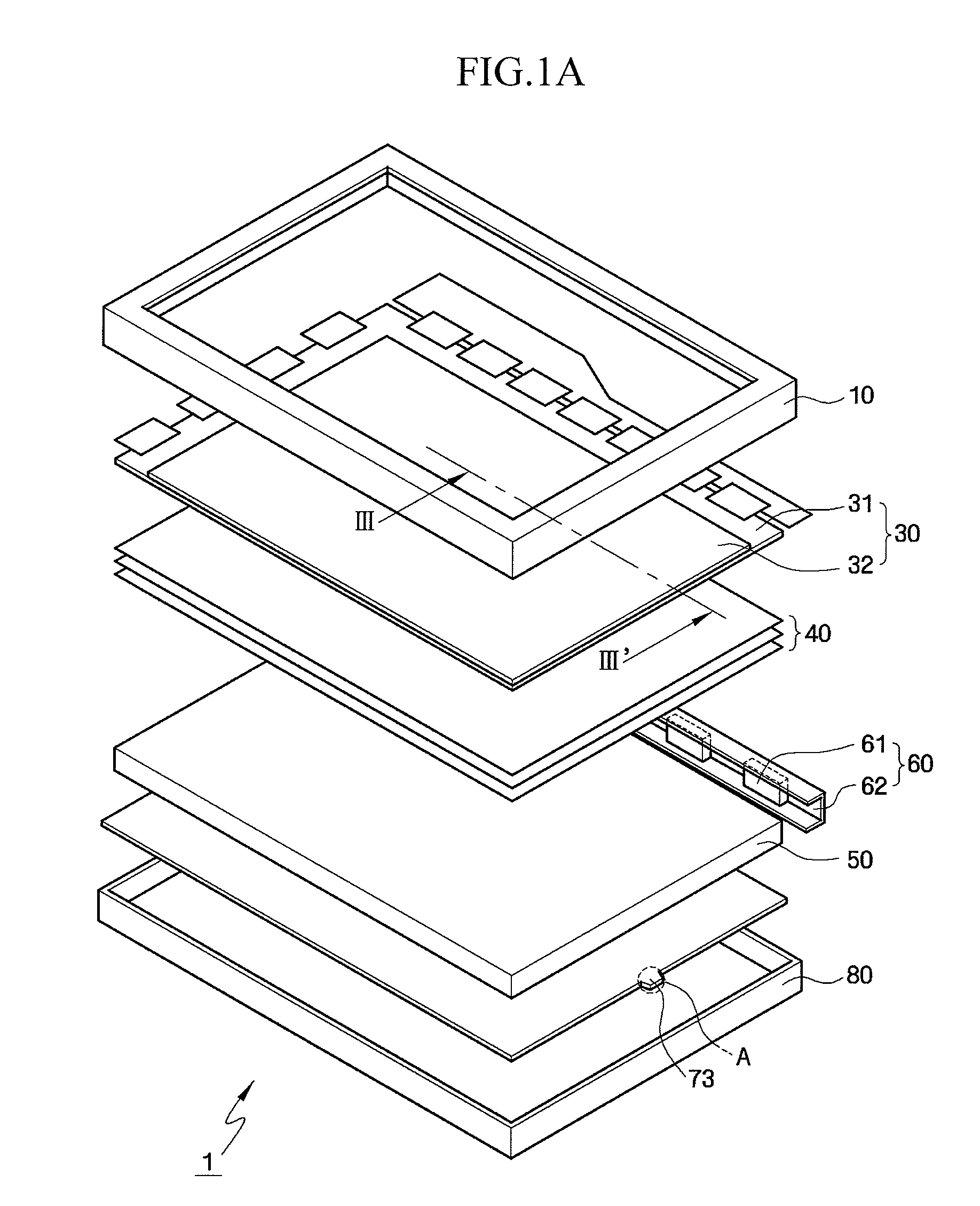
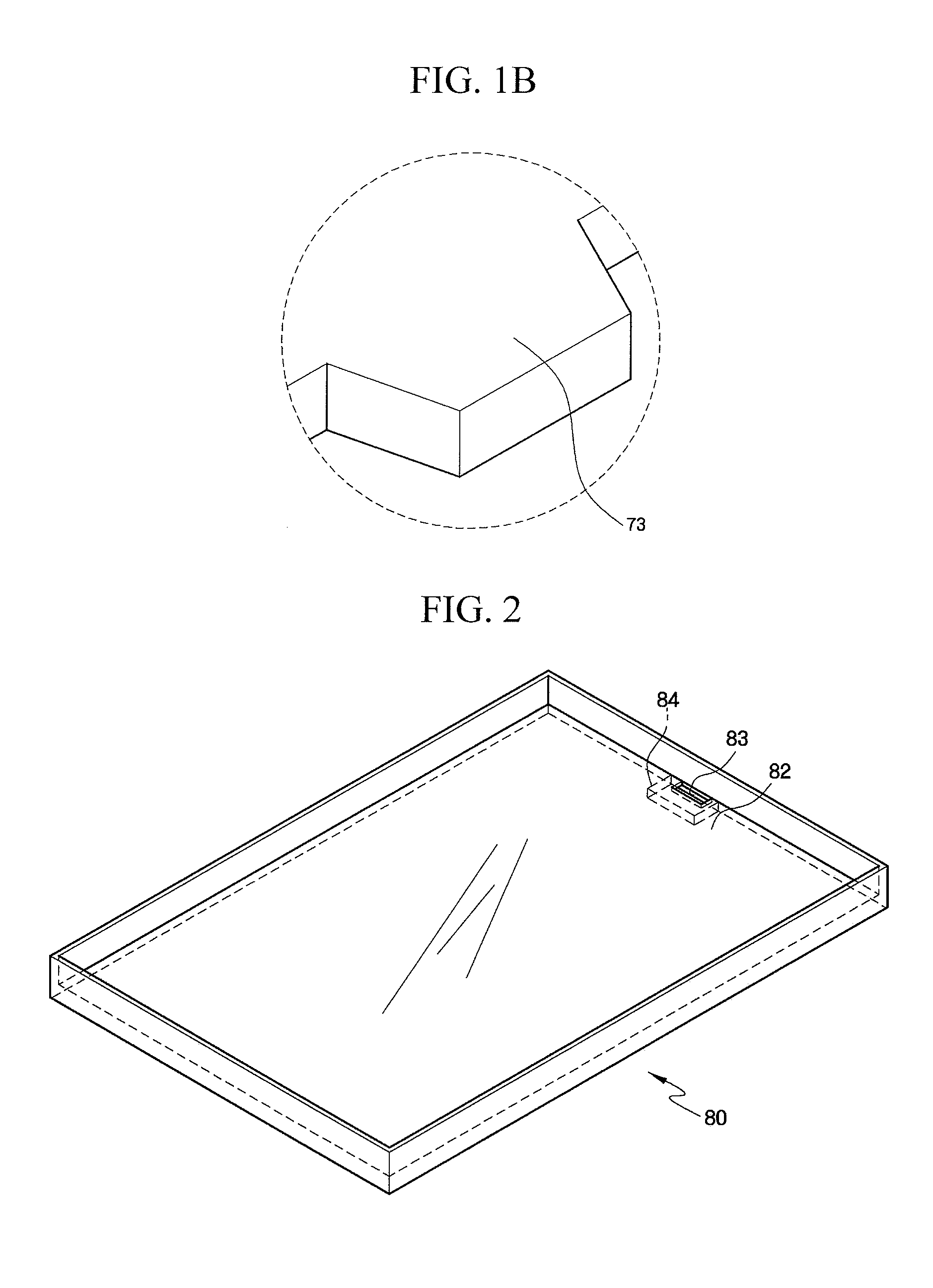
[0028]Referring to FIGS. 1 to 3, a display device according to an embodiment of the present invention will be described in further detail. FIG. 1A is an exploded perspective view of a display device according to an embodiment of the present invention, and FIG. 1B is an enlarged view of a region “A” in FIG. 1A. FIG. 2 is a partial perspective view of a lower receptacle included in the display device of FIG. 1A, and FIG. 3 is a sectional view of the display device, taken along line III-III′ of FIG. 1A.

[0029]Referring to FIGS. 1-3, a display device 1, according to an embodiment of the present invention,...


PUM


Abstract

A display device is provided, which can precisely control a light source by measuring the quantity of light from the light source under uniform conditions. The display device includes a display panel displaying an image, a light source generating light, a light guide plate guiding and providing the light to the display panel, a receptacle accommodating the light source and the light guide plate, an optical sensor fixed to the receptacle to sense the light, a light receiving hole formed at an edge of the receptacle to provide a path through which the light reaches the optical sensor, and an optical adjustment member interposed between the light guide plate and the optical sensor to reduce luminance of the light incident to the optical sensor. The optical sensor is completely exposed to the optical adjustment member through the light receiving hole.

Description

CROSS-REFERENCE TO RELATED APPLICATION[0001]This application claims priority from Korean Patent Application No. 10-2008-0086327, filed on Sep. 2, 2008, in the Korean Intellectual Property Office, the disclosure of which is incorporated by reference herein in its entirety.BACKGROUND OF THE INVENTION[0002]1. Technical Field[0003]The present invention relates to a display device, and more particularly to a display device that can precisely control a light source by measuring the quantity of light from the light source under uniform conditions.[0004]2. Discussion of Related Art[0005]A liquid crystal display (LCD), which is one of the most widely used types of flat panel displays (FPDs), includes two substrates, on which electrodes are formed, and a liquid crystal layer interposed between the two substrates. In such a liquid crystal display, an image is displayed when liquid crystal molecules of the liquid crystal layer are rearranged in accordance with voltages being applied to the elec...

Claims


Application Information

Patent Timeline
Patent Type & Authority Patents(United States)
IPC IPC(8): F21V7/04
CPCG02F1/13318G09G2320/0666G09G3/3406G02F1/133615G02B6/0011G09G2360/145G02B6/0081G02F1/133G02F1/1335
Inventor HONG, HYUN-SEOKLEE, YO-HANHA, SU-HAG
Owner SAMSUNG DISPLAY CO LTD
Learn More