
Method for manufacturing display panel

a technology for display panels and manufacturing methods, applied in the manufacture of electrode systems, electric discharge tubes/lamps, instruments, etc., can solve the problems of increasing the cost of display panels, and achieve the effects of preventing the drying of the surface of display materials, preventing the degradation of display quality, and small cos

Inactive Publication Date: 2014-05-13
KONICA MINOLTA INC
View PDF8 Cites 0 Cited by
  • Summary
  • Abstract
  • Description
  • Claims
  • Application Information

AI Technical Summary

Benefits of technology

This approach effectively reduces volatilization and maintains display quality by ensuring the display material remains moist, preventing surface drying and contamination, while simplifying the process and reducing costs.

Problems solved by technology

However, in the method of Patent Document 1, the display material spilled out during the stacking contaminates the periphery of the substrate, and the contamination may cause problems at the time of assembling a drive circuit in the later step.
In addition, according to the method of Patent Document 2, the manufacturing process is complicated, and a complex device is needed for the control of the degree of vacuum, thereby resulting in a cost increase of the display panel.

Method used

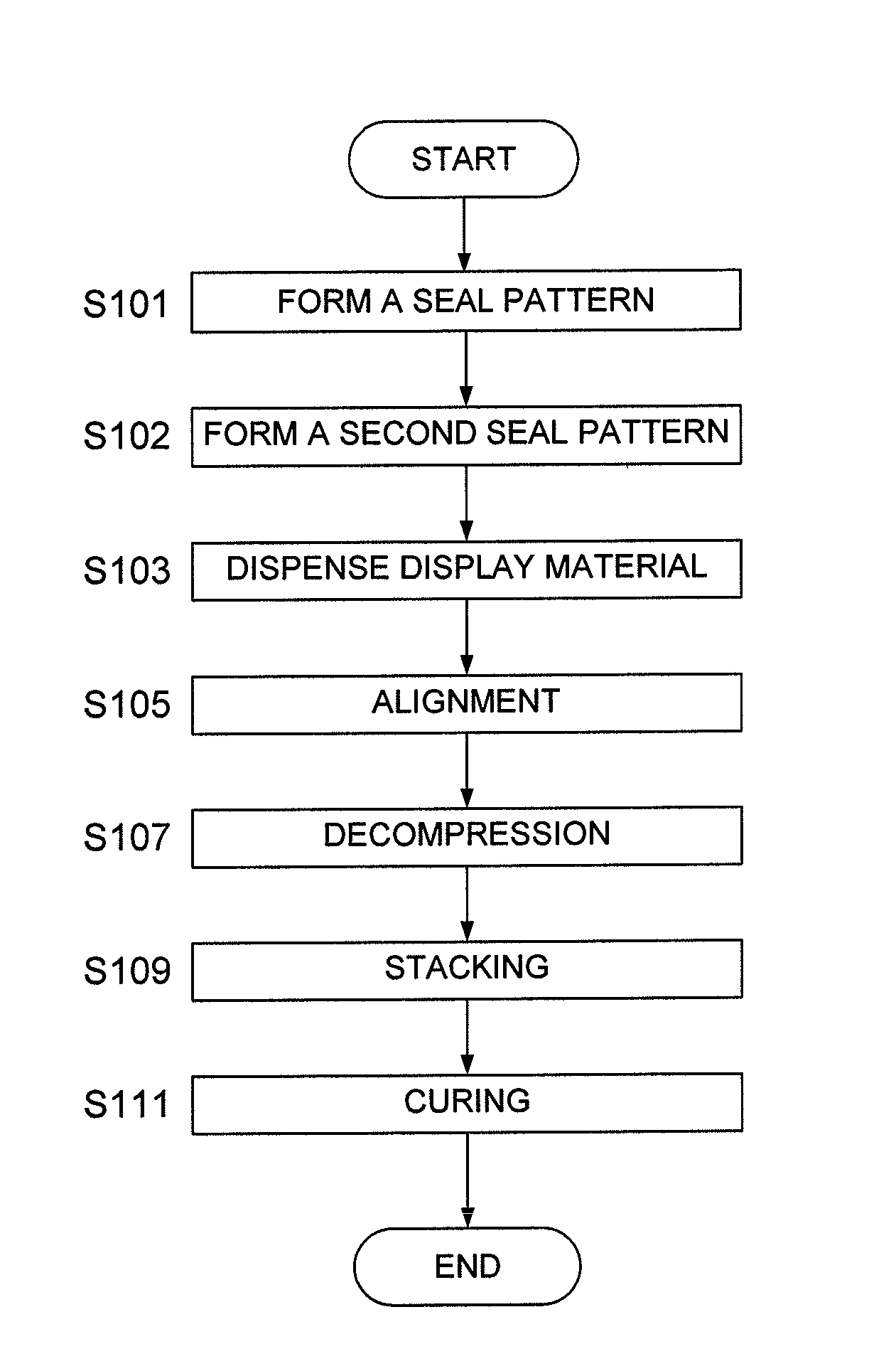
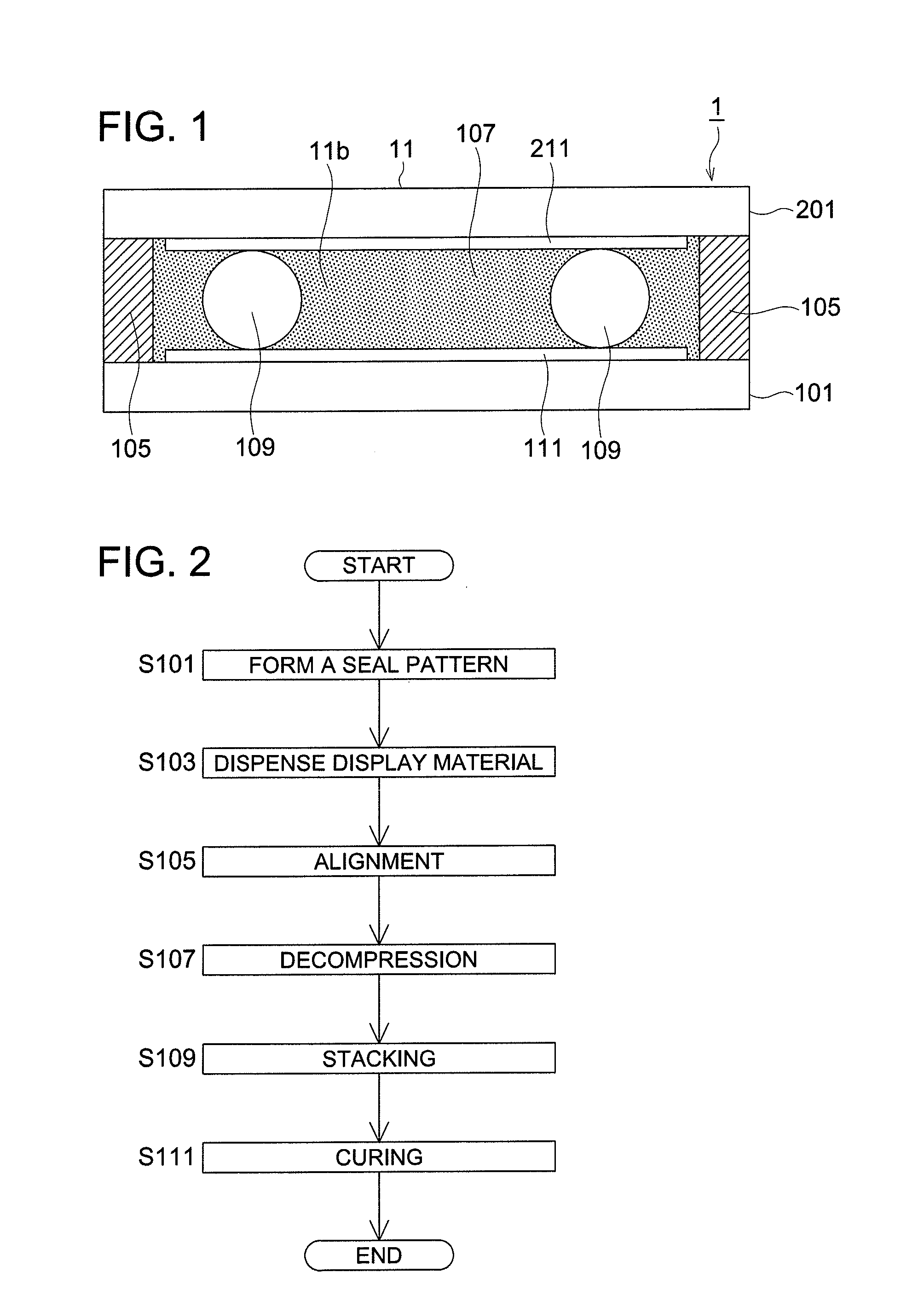
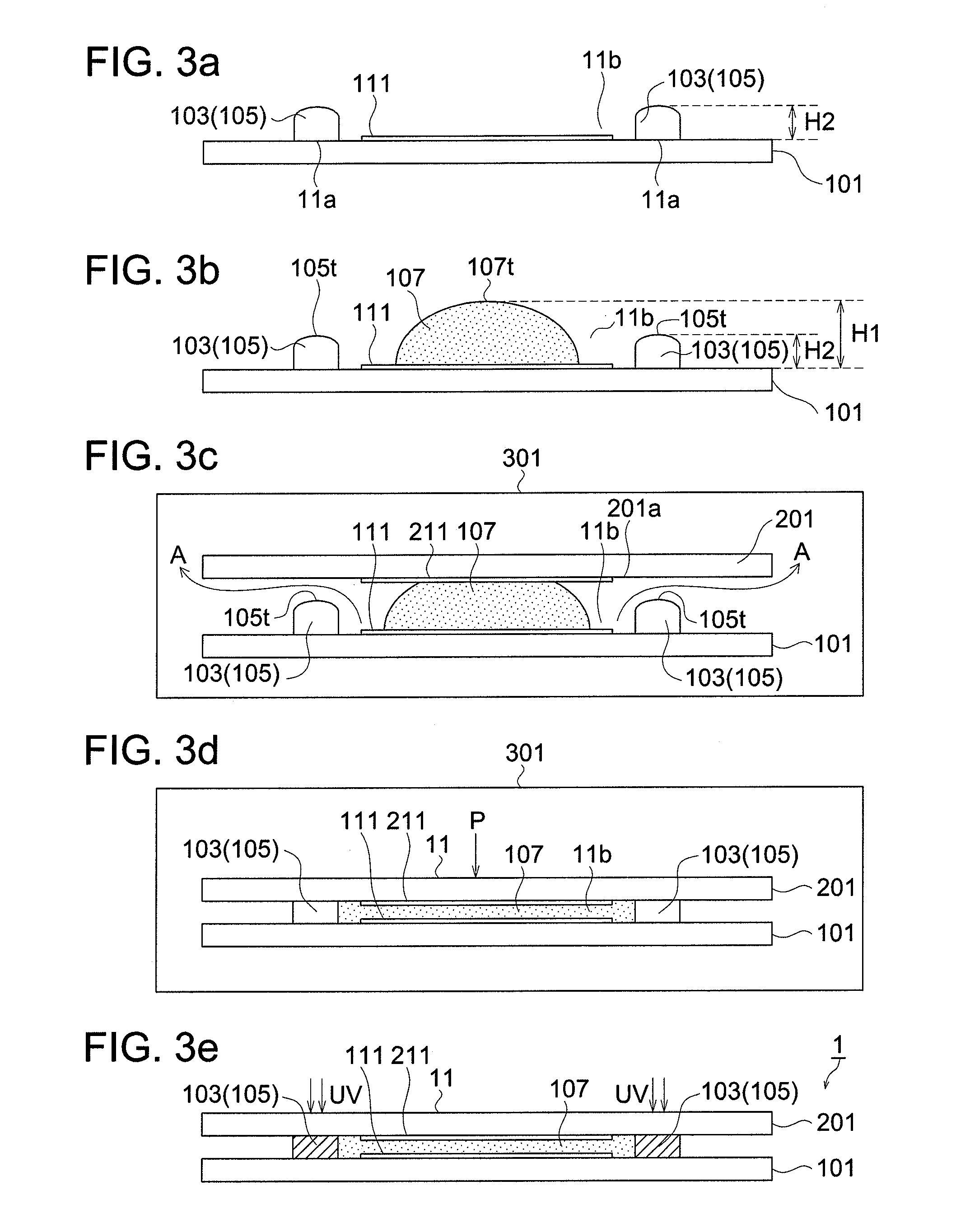

Image

  • Method for manufacturing display panel
  • Method for manufacturing display panel
  • Method for manufacturing display panel

Examples


Embodiment Construction

[0093]Table 1 shows dispense amount of the display material 107, and the volatilization amount and the volatilization proportion of the solvent in display material 107 before and after step S107 (decompression step), with respect to the six display panels 1 produced as working examples by the above-described first embodiment of the method of manufacturing a display panel.

[0094]In addition, the table shows the dispense amount of the display material 107, and the volatilization amount and the volatilization proportion of the solvent in display material 107 before and after the decompression in the vacuum chamber, with respect to six display panels 1 produced as comparative example by a conventional method, shown in FIGS. 7a-7d, of manufacturing a display panel. In the process, conditions for both of the working examples and the comparative examples are that the distance between the apex in height direction of the seal pattern and the opposing substrate was 70 μm, and the compression p...


PUM

PropertyMeasurementUnit
boiling pointaaaaaaaaaa
particle sizeaaaaaaaaaa

Abstract

Disclosed is a method for manufacturing a display panel, which employs a vacuum bonding method. A display material is dispensed such that the height distance from the upper surface of a lower substrate to the top of the display material is larger than the height distance from the surface of either upper or lower substrate on which the seal pattern is formed to the apex of the seal pattern. The upper substrate is placed at a position where the upper substrate and the top of the display material in the height direction are in touch with each other and the seal pattern on one substrate is not in touch with the other substrate, then, air is released. Thus, volatilization of the display material is reduced easily at small cost to prevent drying of the surface of the display material, and the display qualities can be prevented from being degraded.

Description

RELATED APPLICATIONS[0001]This application is a U.S. National Phase Application under 35 USC 371 of International Application PCT / JP2010 / 059662 filed Jun. 8, 2010.[0002]This application claims the priority of Japanese application No. 2009-187021 filed Aug. 12, 2009, the entire content of which is hereby incorporated by reference.TECHNICAL FIELD[0003]The present invention relates to a method for manufacturing a display panel, in particular to a method for manufacturing a display panel in which display material does not easily adversely affected.BACKGROUND ART[0004]In recent years, display devices that are excellent in visibility and have low power consumption are required. Display devices that emit light or modulate light from a self light-emitting body such as CRTs (Cathode Ray Tubes), PDPs (Plasma Display Panels), and LCDs (Liquid Crystal Displays), which are commonly used in these days, are bright and easy to see but have a problem of large power consumption.[0005]From the view po...

Claims


Application Information

Patent Timeline
Patent Type & Authority Patents(United States)
IPC IPC(8): G02F1/15G02F1/17
CPCG02F1/1339G02F1/1341
Inventor HIRAO, YUYAOKADA, MASAKAZU
Owner KONICA MINOLTA INC
Learn More