Stopper structure for rotary operation member, electronic device, and channel stopper

a technology of stopper structure and operation member, which is applied in the direction of resonant circuit driving/adjusting means, resonant circuit tuning, and resonant circuit details, etc. it can solve the problems of limited rotation of the operation member, difficult for the user to correctly determine, and large impact, so as to achieve sufficient axial-direction length and radial-direction width, the effect of increasing the number of parts

Active Publication Date: 2014-05-06
JVC KENWOOD CORP A CORP OF JAPAN
View PDF7 Cites 2 Cited by
  • Summary
  • Abstract
  • Description
  • Claims
  • Application Information

AI Technical Summary

Benefits of technology

[0011]It is a first object of this invention to provide a stopper structure for a rotary operation member which is advantageous in regard to the number of parts, cost, durability, assembling and mounting, and replacement of parts.
[0012]It is a second object of this invention to provide an electronic device which is advantageous in regard to the number of parts, cost, durability, assembling and mounting, and replacement of parts.
[0013]It is a third object of this invention to provide a channel stopper which is advantageous in regard to the number of parts, cost, durability, assembling and mounting, and replacement of parts.
[0018]This invention provides the advantages explained below. A channel stopper is mounted on a rotational shaft, and fits in an axial hole of a rotary operation member. Thus, a sufficiently wide space can be formed between ends of the rotary operation member and the channel stopper and a member surface defining a bottom of an opening through which the rotational shaft extends. The space is used to accommodate an engagement projection provided on the channel stopper and having a sufficient axial-direction length and a sufficient radial-direction width. An increase in the number of parts, an increase in cost, and a decrease in durability are avoided. The channel stopper is prevented from biting into the rotary operation member even in the case where the rotary operation member is made of resin. It is easy to mount the channel stopper on the rotational shaft, and the channel stopper is easily replaced with another.

Problems solved by technology

The user often struggles with an operation part (for example, a rotary operation member) of the device on the belt when using the device.
Thus, in the case where an excessively large number of selectable radio channels is assigned to one rotary operation member, it tends to be difficult for the user to correctly determine which of the channels is being selected when he actuates the rotary operation member.
Firstly, the user struggles with the rotary operation member and rotates the member in one direction until the member contacts a fixed stopper provided on the device.
Secondly, the user struggles with the rotary operation member and rotates the member in a reverse direction until the device tunes in to a desired radio channel.
Rough handling of the rotary operation member causes a great impact when the member comes into contact with the stopper.
In this way, the rotation of the operation member is limited.
In Japanese patent application 2003-337628, the limiting member is formed by the small member, and tends to have a problem with its strength.
The inner circumferential edge of the chassis which defines the opening has a complicated shape so that the chassis is difficult to make.
As the thickness of the stopper is smaller, the strength thereof decreases and the stopper tends to more easily bite into the operation member.
The stopper having a greater thickness however works against the compactness of the radio communication device.

Method used


Image

  • Stopper structure for rotary operation member, electronic device, and channel stopper
  • Stopper structure for rotary operation member, electronic device, and channel stopper
  • Stopper structure for rotary operation member, electronic device, and channel stopper

Examples


Embodiment Construction

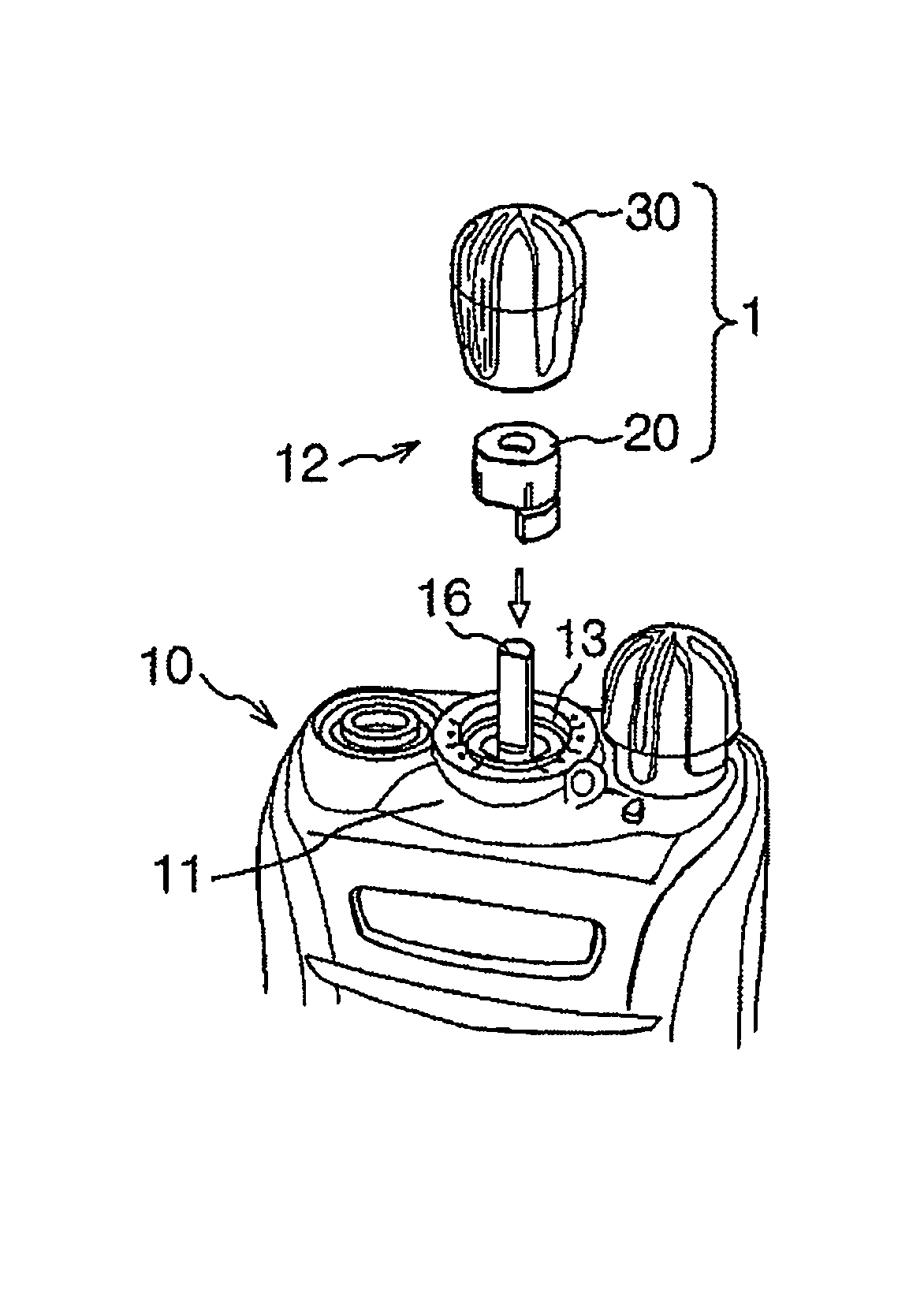
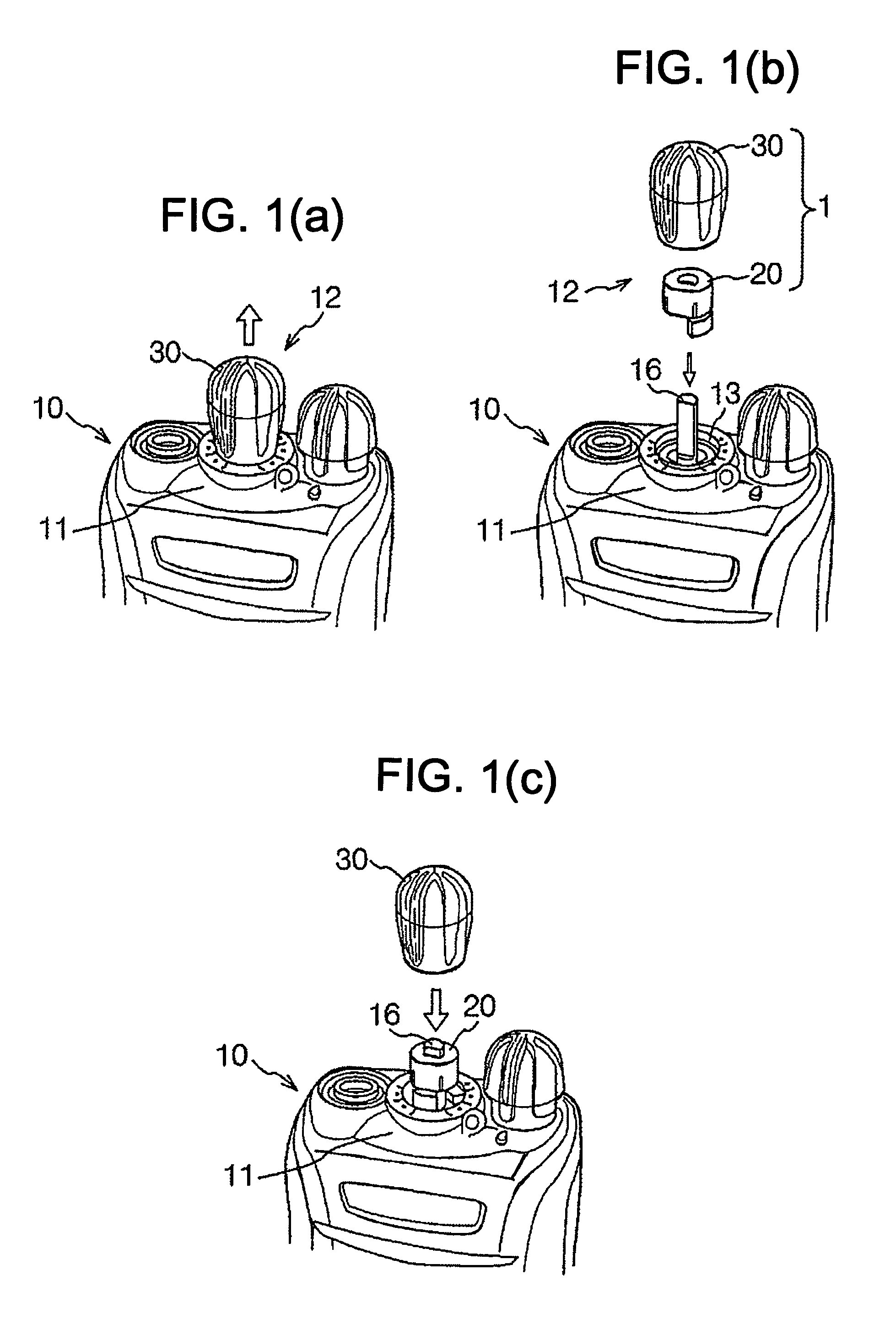
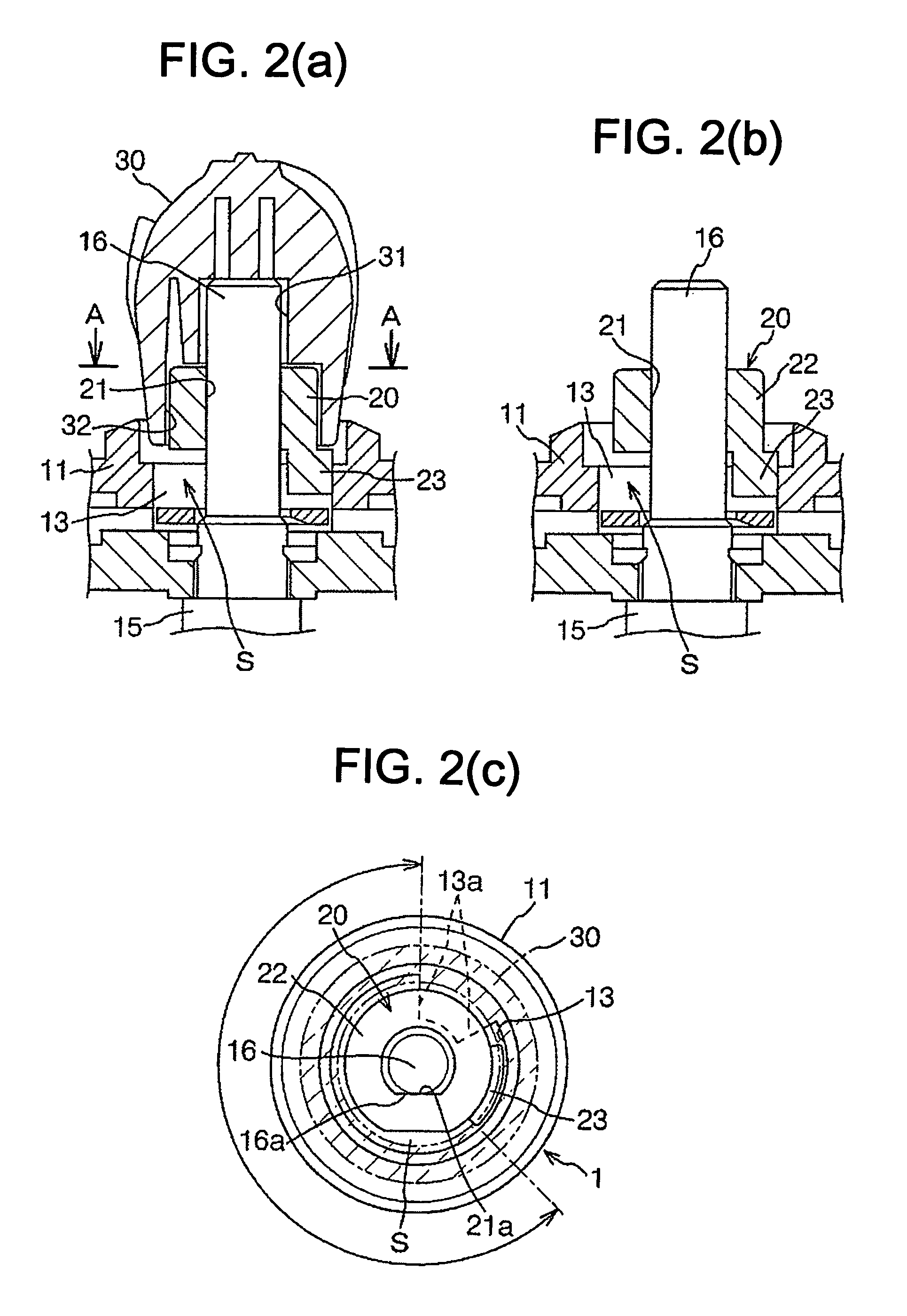
[0024]With reference to FIGS. 1(a)-1(c), an embodiment of a portable radio communication device or an electronic device 10 of the instant invention is shown to have an operation part 12 [FIGS. 1(a), 1(b)] provided with a stopper structure 1. The stopper structure 1 is a means for limiting the range of rotation of a rotary operation member 30 [FIGS. 1(b), 1(c), 2(a) and 2(b)] accessible by a user and designed to operate a rotary encoder switch (a rotary electronic component) 15 [FIGS. 2(a) and 2(b)] in the radio communication device 10. The rotary encoder switch 15 is supported by the body or chassis of the radio communication device 10. The range of rotation of the rotary operation member 30 determines the number or range of radio channels usable by the radio communication device 10.

[0025]The rotary operation member 30 is included in the operation part 12 of the radio communication device 10, and is connected with the rotary encoder switch 15. The stopper structure 1 is designed to ...


PUM


Abstract

A stopper structure includes a wall defining an opening. A rotary electronic component has a rotational shaft extending through the opening. A channel stopper has a tubular body and an engagement projection. The tubular body is detachably mounted onto the rotational shaft and is inhibited from rotating relative thereto. The engagement projection extends from an end of the tubular body in an axial direction and a radial direction with respect to the rotational shaft. A rotary operation member is detachably mounted onto the rotational shaft and the tubular body and is inhibited from rotating relative thereto. The rotary operation member has an axial hole in which at least portions of the rotational shaft and the tubular body fit. A limiting portion provided on the wall is engageable with the engagement projection for limiting a range of rotation of the rotational shaft.

Description

BACKGROUND OF THE INVENTION[0001]1. Field of the Invention[0002]This invention relates to a stopper structure for limiting the range of rotation of a rotary operation member designed to operate, for example, a rotary encoder switch provided in a radio communication device and used to change radio channels. This invention further relates to an electronic device and a channel stopper.[0003]2. Description of the Related Art[0004]Some business-use radio communication devices or portable radio communication devices have rotary encoder switches for changing radio channels. The rotary encoder switches each have a rotational shaft. As the rotational shaft is rotated, the radio channel is changed.[0005]It is known to mount a rotary operation member accessible by a user on the rotational shaft of a rotary encoder switch. As the rotary operation member is rotated by the user, the encoder shaft also is rotated so that the radio channel is changed. Thus, the user can tune the related device to a...

Claims


Application Information

Patent Timeline
Patent Type & Authority Patents(United States)
IPC IPC(8): H03J1/06
CPCH01H19/03
Inventor YAMADA, TADAHIROOTA, SHOJI
Owner JVC KENWOOD CORP A CORP OF JAPAN
Why Eureka
Try Eureka