Inductively coupled plasma source as an electron beam source for spectroscopic analysis

a plasma source and electron beam technology, applied in the field of inductively coupled plasma sources, can solve the problems of limiting the beam current to a low beam current at high resolution, consuming up to 30 minutes or more, and user facing a lengthy process

Active Publication Date: 2014-05-06
FEI CO
View PDF17 Cites 7 Cited by
  • Summary
  • Abstract
  • Description
  • Claims
  • Application Information

AI Technical Summary

Benefits of technology

[0015]The foregoing has outlined rather broadly the features and technical advantages of the present invention in order that the detailed description of the invention that follows may be better understood. Additional features and advantages of the invention will be described hereinafter. It should be appreciated by those skilled in the art that the conception and specific embodiments disclosed may be readily utilized as a basis for modifying or designing other structures for carrying out the same purposes of the present invention. It should also be realized by those skilled in the art that such equivalent constructions do not depart from the spirit and scope of the invention as set forth in the appended claims.

Problems solved by technology

A liquid metal ion source (LMIS) is very bright and can provide high resolution processing, but is limited to a low beam current at high resolution.
For example, electron beam columns typically uses magnetic focusing lenses because of their lower aberration, whereas ion beam columns typically use electrostatic focusing lenses because an excessively large current would be required to focus the heavy ions using a magnetic lens.
If two separate instruments are used, the user is faced with a lengthy process of removing the sample from the FIB system and then setting up the sample in the EDS capable system which can take upwards of 30 minutes or more.
This makes for an unacceptably long time for many applications to be able to analyze a prepared sample.
A dual column system is costly because of the two separate focusing columns.
While it is known that a plasma chamber can be used as a source of electrons as well as ions, plasma sources are not typically used for an SEM because the large virtual source size makes for poor resolution compared to other sources.
Lastly, because the difference in the configuration of the optical columns for focusing electron and focusing ions, using the same column for both ions and electrons would result in less than optimum resolution for ions, electrons, or both.

Method used


Image

  • Inductively coupled plasma source as an electron beam source for spectroscopic analysis
  • Inductively coupled plasma source as an electron beam source for spectroscopic analysis
  • Inductively coupled plasma source as an electron beam source for spectroscopic analysis

Examples


Embodiment Construction

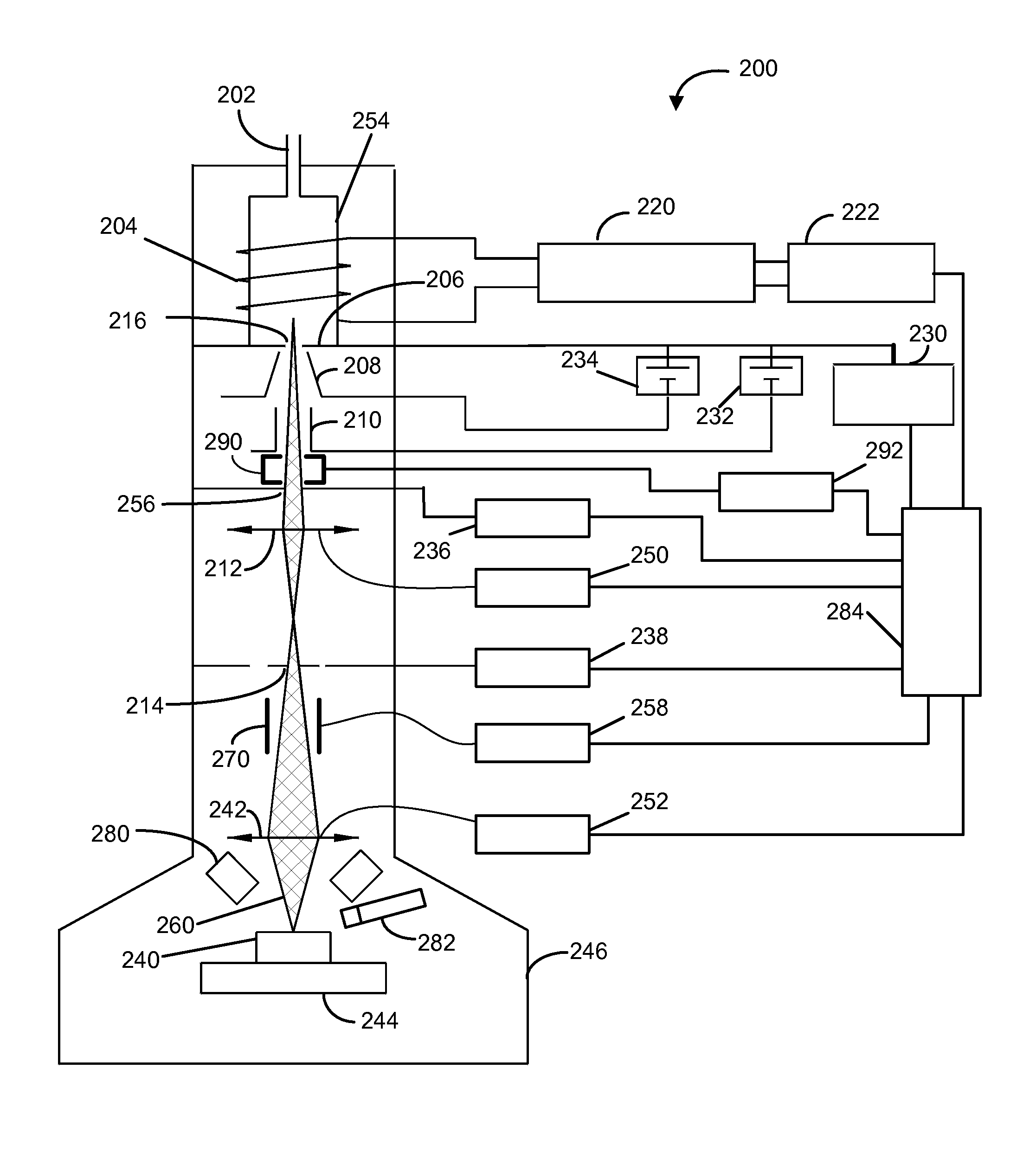
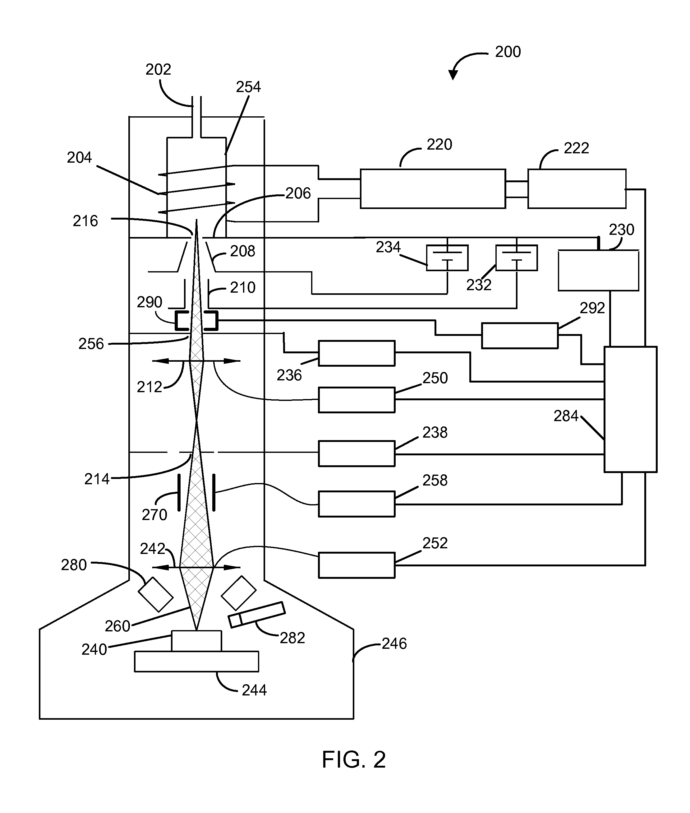
[0021]While it is known that the resolution of an electron beam from a plasma electron source is poorer than the resolution of an electron beam from a thermionic or field emission source, applicants have recognized that beam resolution is not the limiting factor in many applications, such as EDS. In scanning electron microscopy, secondary electrons used to form the image come from a relatively small interaction volume around the impact point of the primary beam. As the beam electrons penetrate beneath the sample surface, they are scattered randomly away from the beam's point of impact. Only secondary electrons generated near the top surface are capable of escaping and being detected, and those secondary electron typically come from close to the point of impact of the primary beam. X-rays, on the other hand, can escape from a much greater depth and so detectable x-rays continue to be generated as the electron moves downwards and is scattered sideways. Thus, the “interaction volume,” ...


PUM


Abstract

A single column inductively coupled plasma source with user selectable configurations operates in ion-mode for FIB operations or electron mode for SEM operations. Equipped with an x-ray detector, energy dispersive x-ray spectroscopy analysis is possible. A user can selectively configure the ICP to prepare a sample in the ion-mode or FIB mode then essentially flip a switch selecting electron-mode or SEM mode and analyze the sample using EDS or other types of analysis.

Description

TECHNICAL FIELD OF THE INVENTION[0001]The present invention relates to charged particle beam systems and, in particular, to the use of an inductively coupled plasma source to provide electrons or ions to process and analyze a sample.BACKGROUND OF THE INVENTION[0002]Focused charged particle beam systems, such as ion and electron beam systems, are used to image, analyze, and modify samples on a microscopic or nanoscopic scale. An electron beam, for example, can be used in a scanning electron microscope (SEM) to form images of a sample by the detection of secondary electrons and for elemental analysis by measuring an x-ray spectrum. A focused ion beam (FIB) system, for example, can be used in a variety of applications in nanotechnology and integrated circuit manufacturing to create and alter microscopic and nanoscopic structures. FIB systems can be used, for example, to image, mill, deposit, and analyze with great precision. Milling or micromachining involves the removal of bulk materi...

Claims


Application Information

Patent Timeline
Patent Type & Authority Patents(United States)
IPC IPC(8): H01J49/08H01J49/10H01J37/30
CPCH01J37/077H01J37/304H01J37/3056H01J2237/0817H01J37/08H01J2237/31749H01J37/05H01J27/16H01J2237/24415H01J37/265G01T1/28H01J37/30H01J37/10H01J37/1471H01J37/285H01J37/305H01J2237/2445H01J2237/24475H01J2237/2448
Inventor ROUTH, JR., BRIAN, ROBERTS
Owner FEI CO
Why Eureka
Try Eureka