
Device for explosive forming

a technology of explosive forming and forming parts, which is applied in the direction of manufacturing tools, forging presses, non-electric welding apparatus, etc., can solve the problems of prolonging the service life of the ignition mechanism, and achieve the effect of promoting development and growth and easy maintenan

Active Publication Date: 2014-05-06
MAGNA INTERNATIONAL INC
View PDF137 Cites 5 Cited by
  • Summary
  • Abstract
  • Description
  • Claims
  • Application Information

AI Technical Summary

Benefits of technology

The invention aims to improve a device by making it easier for a good detonation wave to develop, promoting a more organized explosion process, and making the ignition mechanism last longer.

Problems solved by technology

Surprisingly, the heavy reduction of the reflected shock wave already results in an extension of the service life of the ignition mechanism.

Method used


Image

  • Device for explosive forming
  • Device for explosive forming
  • Device for explosive forming

Examples


Embodiment Construction

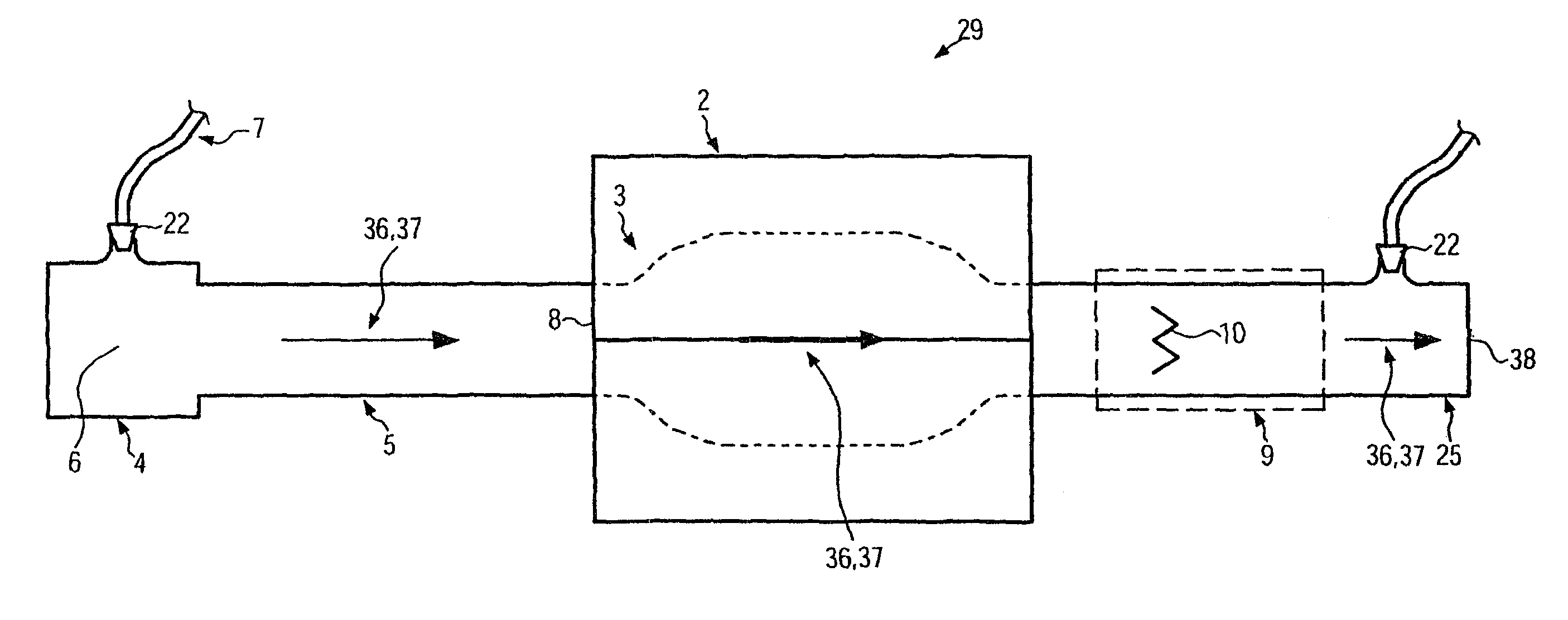
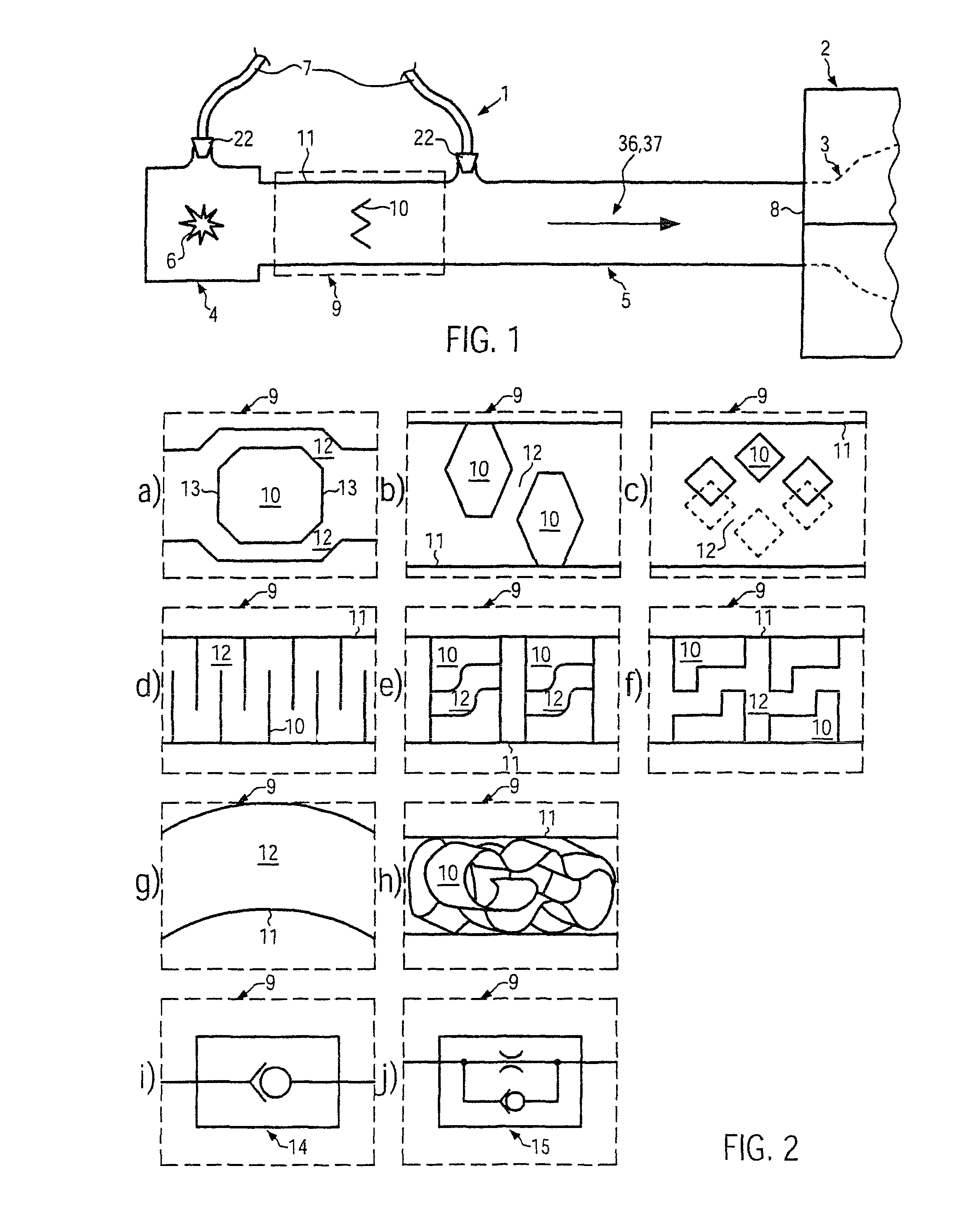
[0063]FIG. 1 illustrates an ignition device 1 for the explosive forming of a work piece 3 inserted in a forming tool 2. The outline of the work piece 3 is thereby indicated with a dotted line, and the forming tool 2 is illustrated separated into an upper and a lower half. Ignition device 1 is comprised of an ignition mechanism 4 and an ignition chamber 5, which in this embodiment connects directly to the ignition mechanism 4 taking the form of an ignition tube. The ignition mechanism 4 has an ignition location 6, symbolically illustrated in this figure with an ignition spark, where the explosion agent is ignited. The explosion agent reaches the ignition mechanism 4 via at least one of the explosion agent feeders 7 after passing a valve 22. The explosion agent ignited in ignition location 6 expands with an explosion front into the ignition chamber 5, and the explosion front exits said ignition chamber via ignition chamber outlet 8, which is adjacent to forming tool 2, and work piece ...


PUM

PropertyMeasurementUnit
flow resistanceaaaaaaaaaa
areaaaaaaaaaaa
propagation volumeaaaaaaaaaa

Abstract

The invention relates to a device for explosive forming of workpieces, comprising an ignition chamber and an ignition mechanism, wherein an explosive agent can be ignited at an ignition location in the ignition chamber using the ignition mechanism, and an ignition chamber outlet is provided, to be improved such that the ignition mechanism has a longer service life. The aim is achieved by a device wherein an impact breaker is provided in the propagation path (37) of the detonation wave.

Description

CROSS-REFERENCE TO RELATED APPLICATIONS[0001]This application is a National Entry Application of PCT / EP08 / 007,901, filed Sep. 19, 2008, which claims priority from German Patent Application Serial No. 102008006979.5, filed on Jan. 31, 2008, entitled “Vorrichtung für das Explosionsumformen” (Device For Explosive Forming), the disclosures of which are incorporated herein by reference for all purposes.FIELD OF THE INVENTION[0002]The invention relates to a device for explosive forming.BACKGROUND OF THE INVENTION[0003]A device of the above-mentioned class is described in WO 2006 / 128519. An ignition tube connects a detonation chamber inside a work piece with a gas supply, exhaust, and ignition device, wherein the ignition device is integrated in the ignition tube. The gas, oxyhydrogen in stoichiometric mixture with low oxygen excess, is ignited by the ignition tube arranged in the ignition device. The explosion of the gas develops a detonation wave, which forms the work piece and then wane...

Claims


Application Information

Patent Timeline
Patent Type & Authority Patents(United States)
IPC IPC(8): B21D26/02
CPCB21D26/08Y10T29/49805Y10T29/49806
Inventor STRANZ, ANDREASZAK, ALEXANDER
Owner MAGNA INTERNATIONAL INC
Learn More