
Non-intrusive processor tracing

a processor and non-intrusive technology, applied in the field of processors, can solve the problems of large amount of trace data captured in real time, increase in the number of pcs per clock cycle, and rapid filling of trace buffers, so as to reduce the interference between separate traffi

Active Publication Date: 2014-04-29
APPLE INC
View PDF11 Cites 20 Cited by
  • Summary
  • Abstract
  • Description
  • Claims
  • Application Information

AI Technical Summary

Benefits of technology

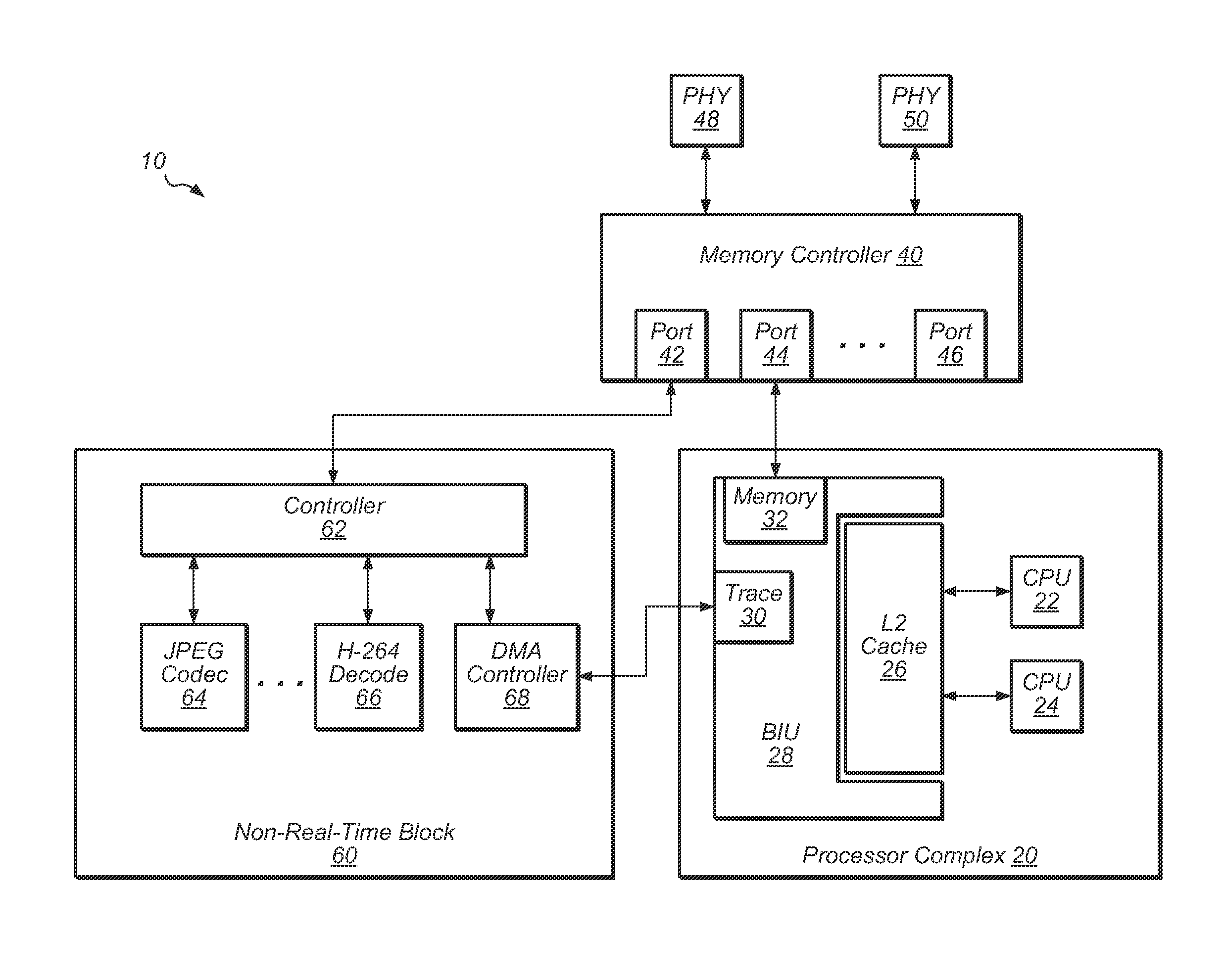
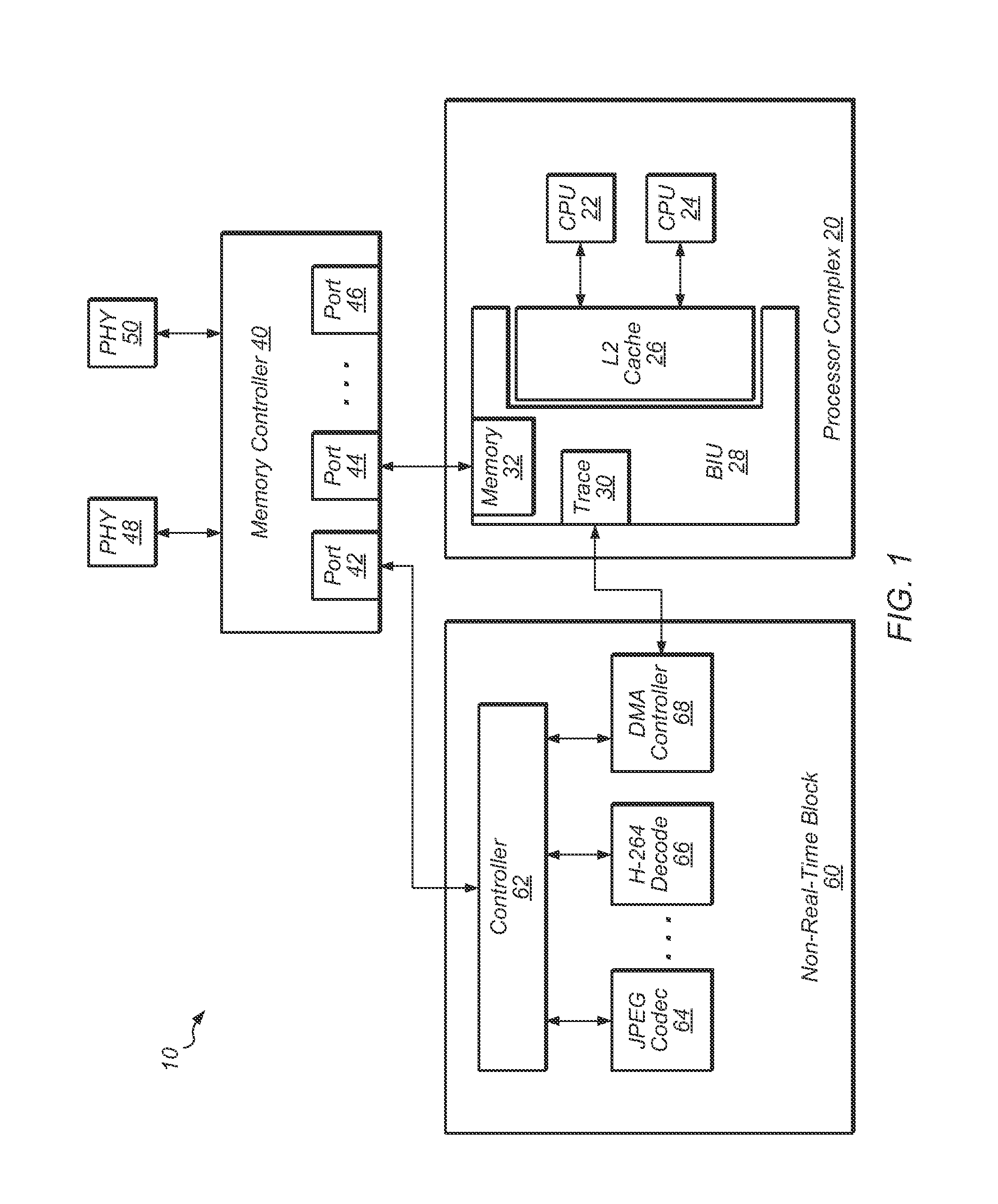
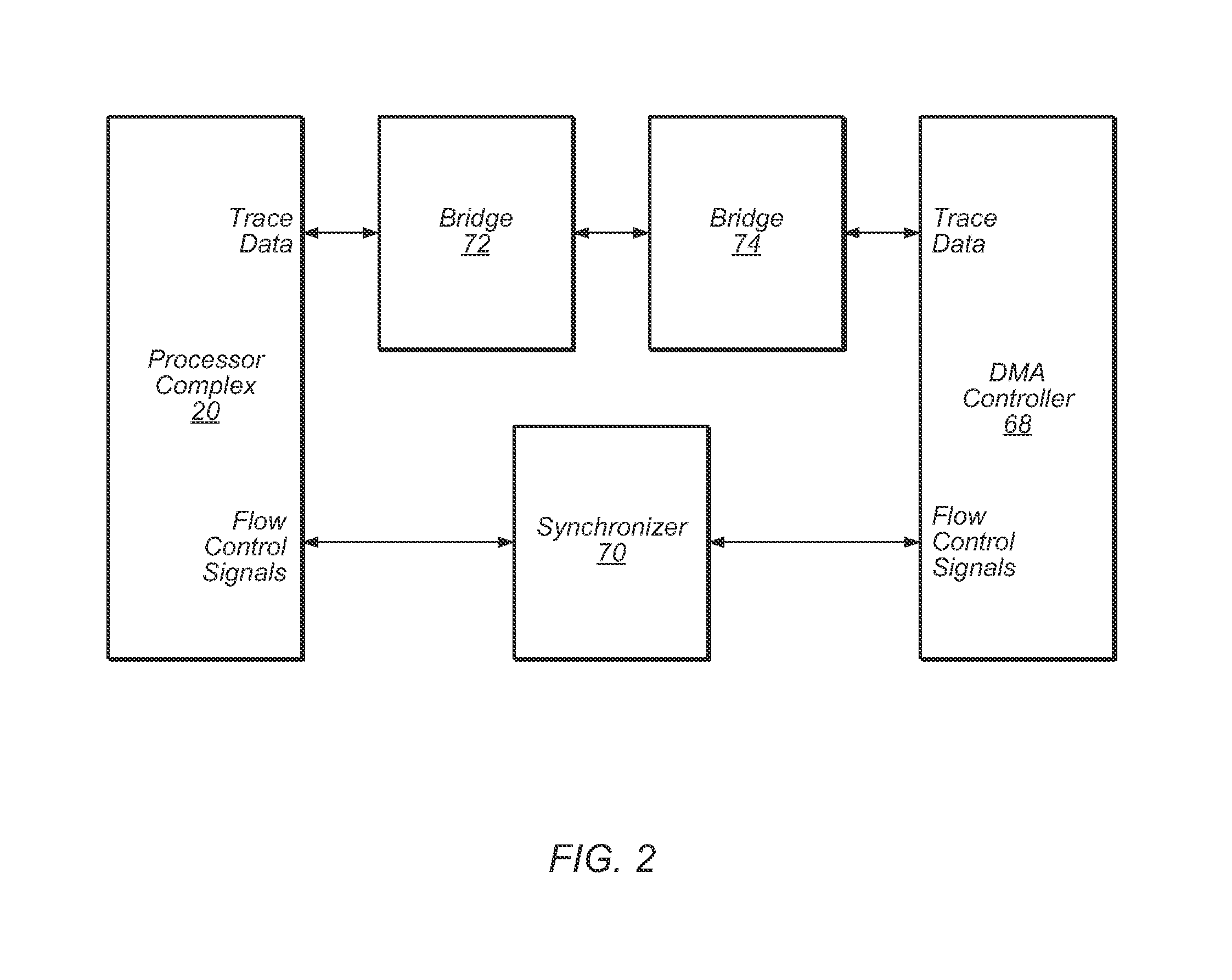
[0008]The NRT block may include a direct memory access (DMA) controller, and the DMA controller may read the data out of the trace buffers. Then, the DMA controller may write the trace data to memory via a memory controller. The DMA controller may be coupled to the memory controller via a NRT port. The processors may also be coupled to the memory controller via a real-time (RT) port. The separation of the processor traffic and trace data traffic on two separate ports of the memory controller may minimize the interference between the separate traffic and may allow trace data to be written to memory without affecting the performance of the processor(s).

Problems solved by technology

As the complexity of the processors and the SoC including the processors increases (superscalar design, multiple cores per chip, etc.), the number of PCs per clock cycle increases.
As a result, the amount of trace data captured in real time expands dramatically, and the trace buffer may fill up rapidly and need to be written to memory on a frequent basis.
Accordingly, the dumping of the trace buffer to memory may interfere with the operation of the processors, which may change the way the processors behave when tracing is enabled versus when tracing is not enabled.

Method used


Image

  • Non-intrusive processor tracing
  • Non-intrusive processor tracing
  • Non-intrusive processor tracing

Examples


Embodiment Construction

[0020]In the following description, numerous specific details are set forth to provide a thorough understanding of the methods and mechanisms presented herein. However, one having ordinary skill in the art should recognize that the various embodiments may be practiced without these specific details. In some instances, well-known structures, components, signals, computer program instructions, and techniques have not been shown in detail to avoid obscuring the approaches described herein. It will be appreciated that for simplicity and clarity of illustration, elements shown in the figures have not necessarily been drawn to scale. For example, the dimensions of some of the elements may be exaggerated relative to other elements.

[0021]While the invention is susceptible to various modifications and alternative forms, specific embodiments thereof are shown by way of example in the drawings and will herein be described in detail. It should be understood, however, that the drawings and detai...


PUM


Abstract

A system, apparatus, and method for writing trace data to storage. Trace data is captured from one or more processors, and then the trace data is written to a trace buffer. The trace data includes program counters of instructions executed by the processors and other debug data. A direct memory access (DMA) controller in a non-real-time block of the system reads trace data from the trace buffer and then writes the trace data to memory via a non-real-time port of a memory controller.

Description

BACKGROUND[0001]1. Field of the Invention[0002]The present invention relates generally to processors, and in particular to capturing and storing processor trace data.[0003]2. Description of the Related Art[0004]Methods and mechanisms have been developed to accumulate debugging information for processors within a system on chip (SoC). Typically, the processors execute programs that interact with other devices within a SoC. A program may comprise one or more instruction sequences, which can include branches within the sequences, branches to other sequences, etc. Each instruction may be identified by an address, or PC, which locates the instruction in memory (indirectly, when address translation is enabled).[0005]During development of the SoC and programs to execute on the SoC, various debugging aids can be useful. For example, the stream of PCs executed by the processor may be useful to determine the program flow. Both functional problem diagnoses (traditional debugging) and performan...

Claims


Application Information

Patent Timeline
Patent Type & Authority Patents(United States)
IPC IPC(8): G06F11/00
CPCG06F11/3471G06F2201/88G06F11/348G06F2201/865G06F11/3636G06F2201/81G06F11/3648
Inventor MILLET, TIMOTHY J.GO, SHUN WAIZIESLER, CONRAD H.
Owner APPLE INC
Learn More