Lens system
a technology of lens and power supply, which is applied in the direction of printers, instruments, cameras focusing arrangement, etc., can solve the problems of limited failure of the camera, and limitation of the power supply capacity of the camera to the lens held by the camera, so as to improve the lens drive characteristics
- Summary
- Abstract
- Description
- Claims
- Application Information
AI Technical Summary
Benefits of technology
Problems solved by technology
Method used
Image
Examples
embodiment 1
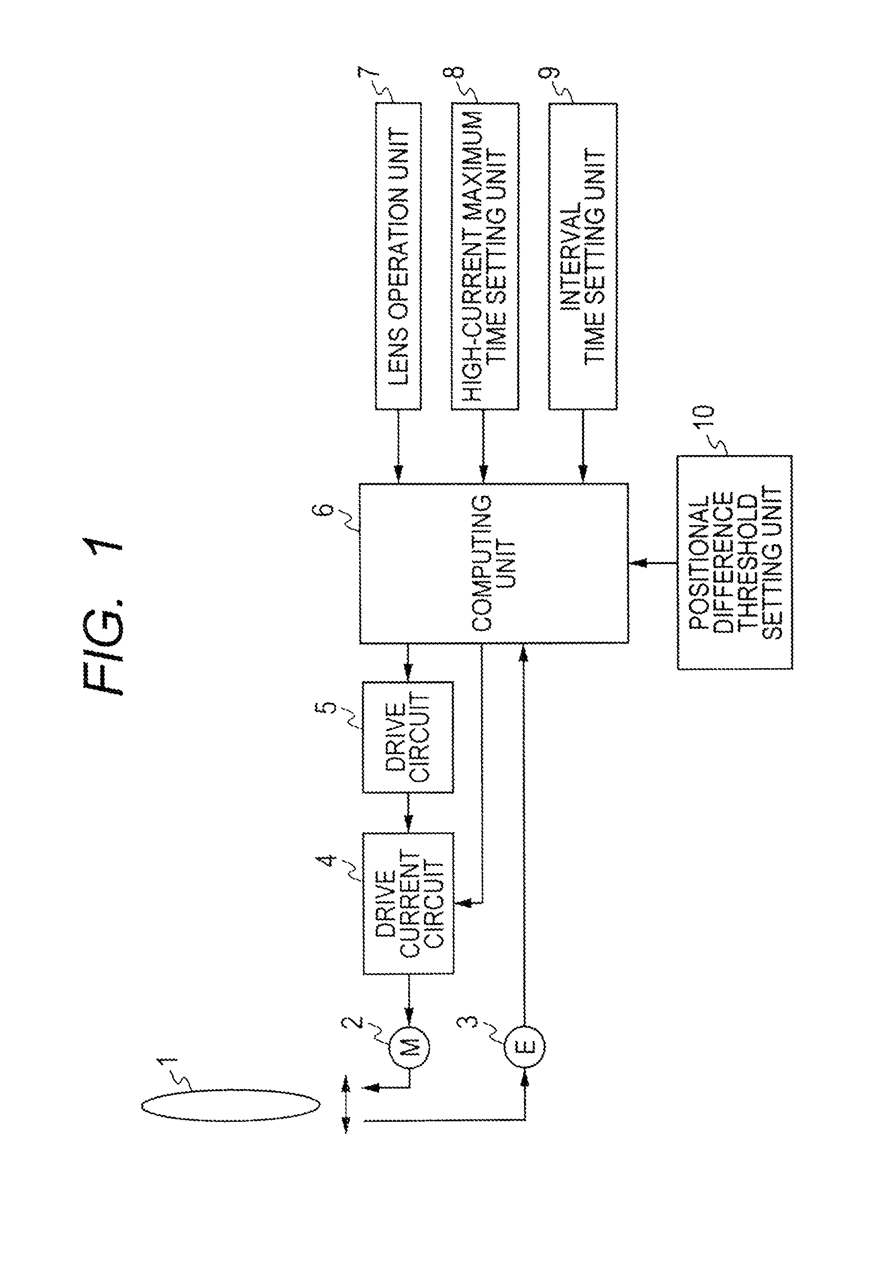
[0024]Hereinafter referring to FIG. 1, a configuration of a lens system of a first embodiment of the present invention is described.
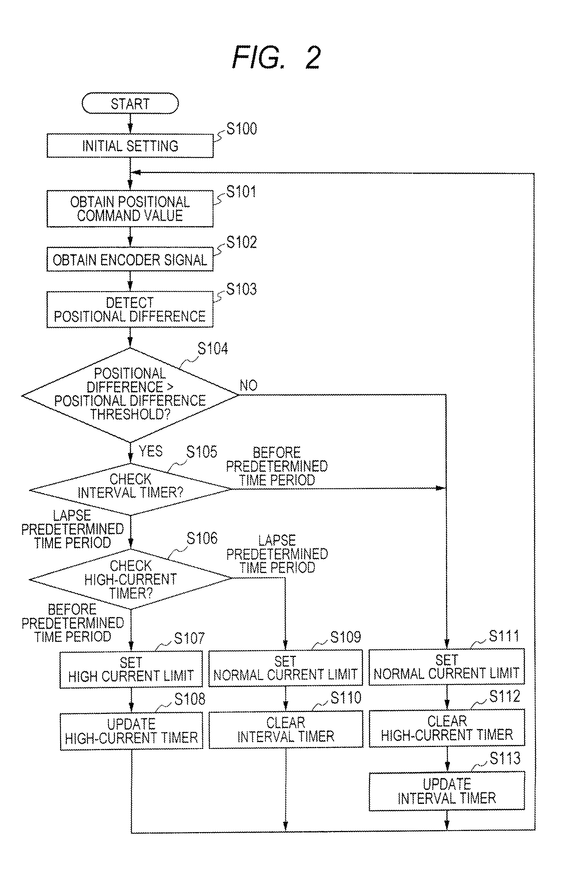
[0025]The lens system of this embodiment includes a lens unit 1, a motor 2 that is a drive unit for driving the lens unit 1 and a position detector 3 for detecting the position of the lens unit 1 in the optical axis direction. The lens system further includes a drive circuit 5 that generates a drive signal for driving the motor 2, and a computing unit 6 that performs computations for controlling the drive of the motor 2. The computing unit 6 outputs a lens operation signal according to an operation by an operator on the lens operation unit 7; the operation corresponds to a drive amount of the lens unit 1 as an object to be driven. A drive current circuit 4 supplies a drive current to the motor 2 based on the drive signal from the drive circuit 5. The drive current circuit 4 can set any one of a first maximum current value serving as a normal state and a...
embodiment 2
[0039]Hereinafter referring to FIG. 3, a configuration of a lens system of a second embodiment of the present invention is described.
[0040]In the lens system of this embodiment, a lens unit 1, a motor 2 that is a drive unit for driving the lens unit 1, a position detector 3 for detecting the position of the lens unit 1 in the optical axis direction, a drive current circuit 4, a drive circuit 5 that generates a drive signal for driving the motor, a computing unit 6 for performing control computation for driving the motor, and a lens operation unit 7 that operates the lens unit 1 as an object to be driven are the same as those in the first embodiment. Accordingly, description thereof is omitted.
[0041]A high-current maximum time that is time during which the maximum current limit for the drive current circuit 4 can continuously be set to the second maximum current value larger than the normal state, and the minimum interval time required to be elapsed between a moment when the maximum ...
embodiment 3
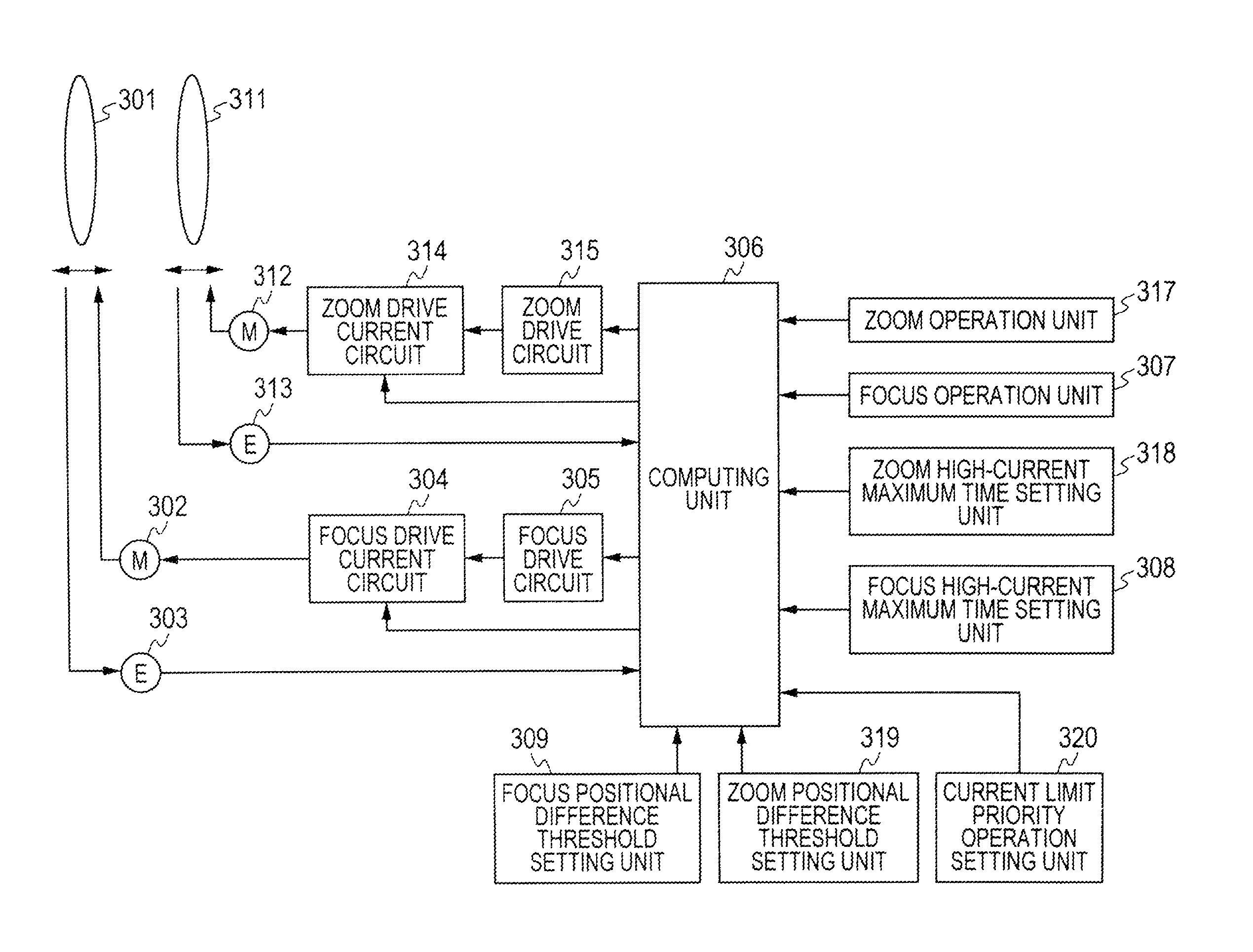
[0056]Hereinafter referring to FIG. 5, a configuration of a lens system of a third embodiment of the present invention is described.
[0057]The lens system of the third embodiment includes a focus lens unit 301 that conducts a focusing function, and a zoom lens unit 311 that conducts a zoom function. The focus lens unit 301 is driven by the focus motor 302. The position of the focus lens unit 301 in the optical axis direction is detected by a focus position detector 303. A focus drive current circuit 304 selects a maximum value of current to be supplied to the focus motor 302 for driving the focus lens unit 301 according to a selection signal output from an after-mentioned computing unit 306. The focus drive circuit 305 as a focus drive unit generates a drive signal for driving the focus motor 302.
[0058]Likewise, the zoom lens unit 311 is driven by a zoom motor 312. The position of the zoom lens unit 311 in the optical axis direction is detected by the zoom position detector 313. A zo...
PUM
 Abstract
Description
Claims
Application Information
 - R&D
- Intellectual Property
- Life Sciences
- Materials
- Tech Scout
- Unparalleled Data Quality
- Higher Quality Content
- 60% Fewer Hallucinations
Browse by: Latest US Patents, China's latest patents, Technical Efficacy Thesaurus, Application Domain, Technology Topic, Popular Technical Reports.
© 2025 PatSnap. All rights reserved.Legal|Privacy policy|Modern Slavery Act Transparency Statement|Sitemap|About US| Contact US: help@patsnap.com


