
Intra-link spatial-mode mixing in an under-addressed optical MIMO system

a spatial-mode mixing and optical mimo technology, applied in the field of optical communication equipment, can solve the problems of not being able to simultaneously couple corresponding modulated optical signals, and not being able to individually address all the supported spatial modes of a typical multi-mode or multi-core. , to achieve the effect of reducing the probability of outage in an under-addressed optical

Active Publication Date: 2014-04-22
ALCATEL LUCENT SAS
View PDF16 Cites 12 Cited by
  • Summary
  • Abstract
  • Description
  • Claims
  • Application Information

AI Technical Summary

Benefits of technology

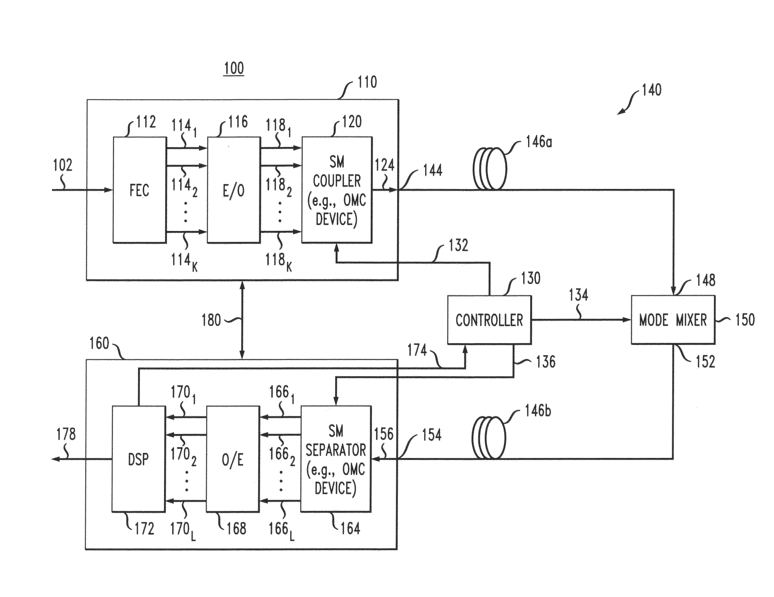
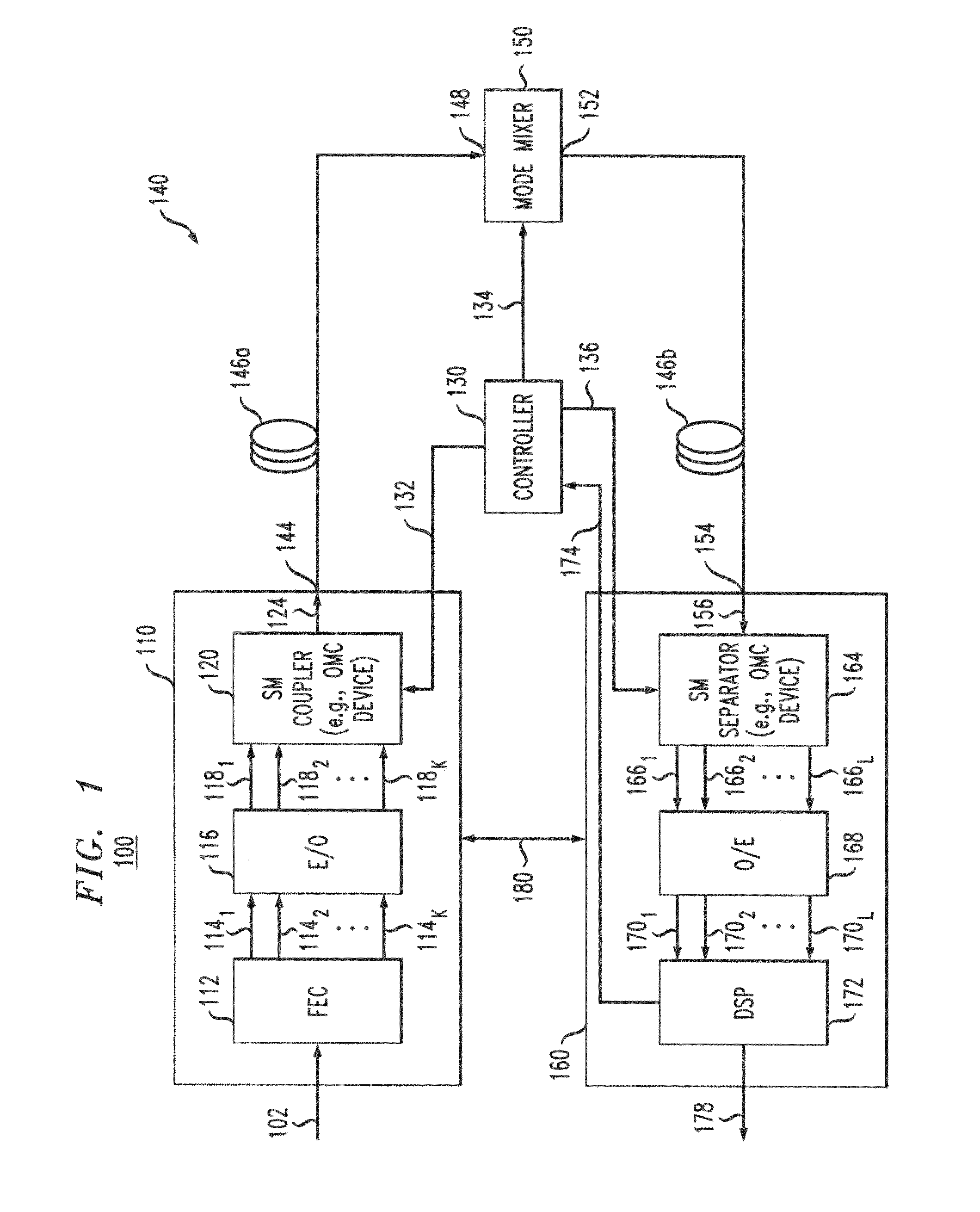
The patent text describes a way to reduce errors in an optical MIMO system by using a device that changes the way light is mixed in the system. This change happens quickly, reducing the likelihood of errors. The system also includes two devices that address different subsets of spatial modes, and an optical mixing subsystem that combines the light from each device to create a more complex pattern. This results in a more complex and accurate pattern of light, improving the overall performance of the system.

Problems solved by technology

Due to certain hardware limitations, a conventional transmitter may not be able to individually address all of the spatial modes supported by a typical multimode or multi-core fiber.
For similar hardware reasons, a conventional receiver also may not be able to individually address all of those supported spatial modes.
As a result, such a transmitter may not be able to simultaneously couple corresponding modulated optical signals into all of the supported spatial modes, and such a receiver may not be able to simultaneously extract corresponding modulated optical signals from all of the supported spatial modes.
Disadvantageously, the optical noise and mode-dependent loss imposed by the fiber-optic link may cause the outage probability in such an under-addressed optical MIMO system to be relatively high.

Method used


Image

  • Intra-link spatial-mode mixing in an under-addressed optical MIMO system
  • Intra-link spatial-mode mixing in an under-addressed optical MIMO system
  • Intra-link spatial-mode mixing in an under-addressed optical MIMO system

Examples


Embodiment Construction

[0044]A multimode fiber can provide a higher transmission capacity than a single-mode fiber, e.g., by means of space-division multiplexing (SDM). More specifically, different guided modes of a multimode fiber can be populated with different modulated optical signals or different linear combinations of a given set of independently modulated optical signals. The original data can then be recovered at the receiver by appropriately de-multiplexing and de-convolving the resulting received optical SDM signal. A similar concept is also applicable to a multi-core fiber. Advantageously, space-division multiplexing can be used to complement other multiplexing techniques, such as time-division multiplexing, wavelength-division multiplexing, orthogonal frequency-division multiplexing, and polarization-division multiplexing, thereby further increasing the accessible transmission capacity of the corresponding optical-transport link.

[0045]As known in the art, a multimode fiber may subject the opti...


PUM


Abstract

The outage probability in an under-addressed optical MIMO system may be reduced by configuring an intra-link optical mode mixer to dynamically change the spatial-mode mixing characteristics of the link on a time scale that is faster than the channel coherence time. Provided that the MIMO system employs an FEC code that has a sufficient error-correcting capacity for correcting the amount of errors corresponding to an average state of the MIMO channel, this relatively fast dynamic change tends to reduce the frequency of events during which the number of errors per FEC-encoded block of data exceeds the error-correcting capacity of the FEC code.

Description

CROSS-REFERENCE TO RELATED APPLICATIONS[0001]This application claims priority from U.S. Provisional Patent Application No. 61 / 449,246, filed Mar. 4, 2011, and entitled “SPATIAL-MODE MANAGEMENT IN UNDER-ADDRESSED OPTICAL MIMO SYSTEMS,” which is incorporated herein by reference in its entirety.[0002]The subject matter of this application is related to that of U.S. patent application Ser. No. 13 / 332,588, by Peter J. Winzer and Gerard J. Foschini, filed on the same date as the present application, and entitled “DYNAMIC SPATIAL-MODE ALLOCATION IN AN UNDER-ADDRESSED OPTICAL MIMO SYSTEM,” which is incorporated herein by reference in its entirety.BACKGROUND[0003]1. Field of the Invention[0004]The present invention relates to optical communication equipment and, more specifically but not exclusively, to equipment for establishing and operating multiple-input / multiple-output (MIMO) optical-transport channels over a multimode or multi-core fiber.[0005]2. Description of the Related Art[0006]Thi...

Claims


Application Information

Patent Timeline
Patent Type & Authority Patents(United States)
IPC IPC(8): G02B6/42
CPCH04L1/004H04B10/2581G02B6/14H04J14/04H04J14/052
Inventor WINZER, PETER J.FOSCHINI, GERARD J.
Owner ALCATEL LUCENT SAS
Learn More