
Motion adaptive deinterlacer

a technology of motion adaptive deinterlacing and video sequence, which is applied in the field of video compression, can solve the problems of blur of reconstructed progressive frame, difficulty in deinterlacing video sequence, and halving vertical resolution

Inactive Publication Date: 2014-04-22
NXP USA INC
View PDF3 Cites 8 Cited by
  • Summary
  • Abstract
  • Description
  • Claims
  • Application Information

AI Technical Summary

Benefits of technology

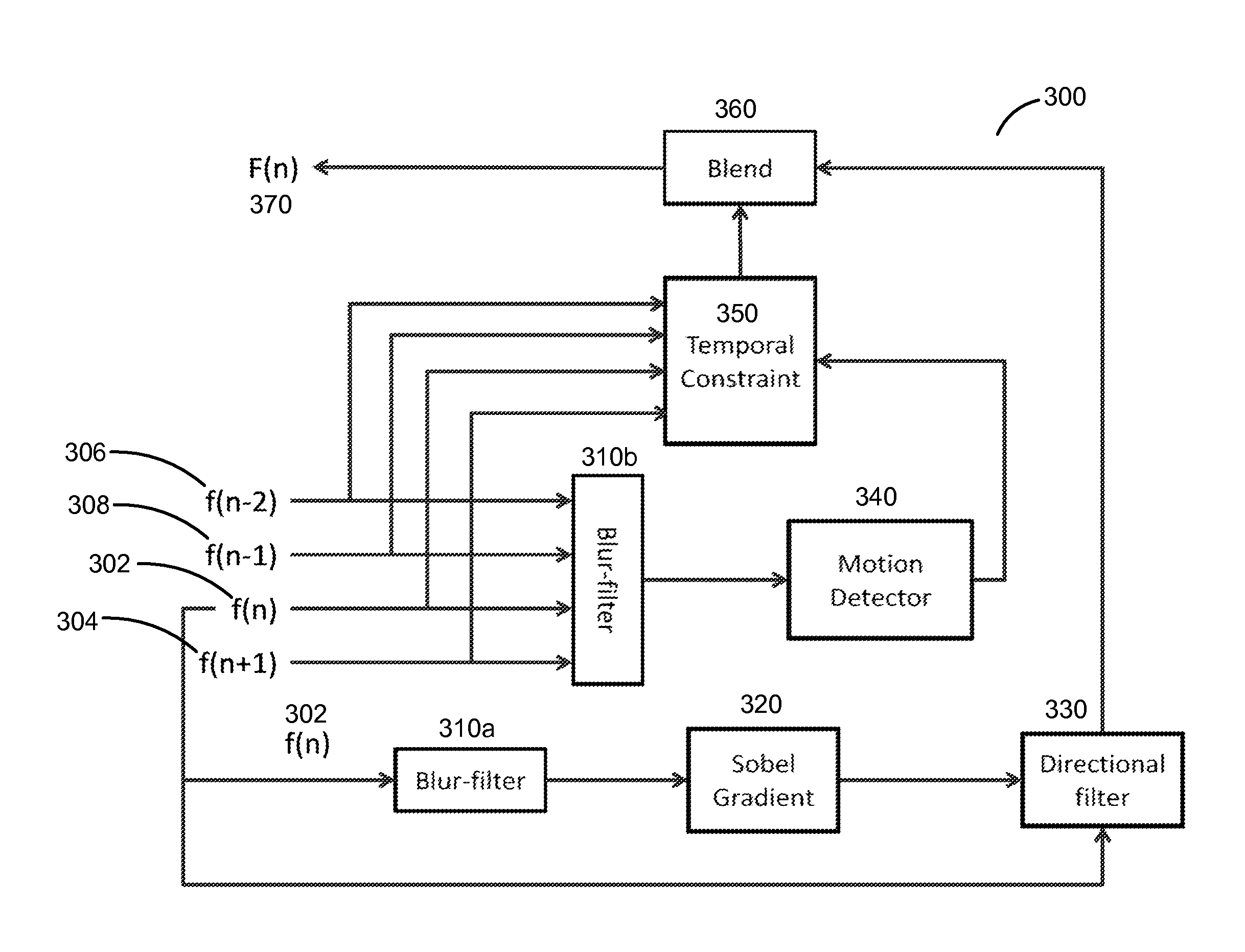
The patent describes a method for effectively converting interlaced video into progressive format for display on devices like plasmas display or projection TVs. The method uses motion adaptive deinterlacing, which filters noise from the interlaced fields using a blur filter and detects edges with a Sobel operator. From these edges, the method selects the direction that provides the smallest difference between the spatial neighboring pixels of an output pixel to spatially interpolate the output pixel. This method provides high quality conversion with balanced tradeoff of computational complexity.

Problems solved by technology

Deinterlacing a video sequence is challenging because visual artifacts can be visible due to defects, such as edge flicker, blur and line-crawling, caused by ineffective deinterlacing.
One disadvantage of deinterlacing using intra-interpolation is the blur of the reconstructed progressive frame because the vertical resolution is halved.
The problem with this method is that the line-crawling effect occurs in the motion area of the progressive frame.

Method used


Image

  • Motion adaptive deinterlacer
  • Motion adaptive deinterlacer
  • Motion adaptive deinterlacer

Examples


Embodiment Construction

[0018]The Figures (FIGS.) and the following description relate to preferred embodiments by way of illustration only. It should be noted that from the following discussion, alternative embodiments of the structures and methods disclosed herein will be readily recognized as viable alternatives that may be employed without departing from the principles of what is claimed.

[0019]Reference will now be made in detail to several embodiments, examples of which are illustrated in the accompanying figures. It is noted that wherever practicable similar or like reference numbers may be used in the figures and may indicate similar or like functionality. The figures depict embodiments of the disclosed system (or method) for purposes of illustration only. One skilled in the art will readily recognize from the following description that alternative embodiments of the structures and methods illustrated herein may be employed without departing from the principles described herein.

Configuration Overvie...


PUM


Abstract

A motion adaptive deinterlacer (MADI) receives two pairs of interlaced fields from a current frame and a reference frame of an input video. The MADI deinterlacer filters noise of the received interlaced fields and detects edges of the received interlaced fields. From the detected edges, the MADI deinterlacer spatially interpolates an output pixel using directional filtering. The MADI deinterlacer also detects motion of the output pixel and calculates temporal constraints of the output pixel based on same parity field difference and / or opposite parity field difference. Based on the temporal interpolation and spatial interpolation of the output pixel, the MADI deinterlacer blends the temporal and spatial interpolation of the output pixel to generate an output pixel in progressive format.

Description

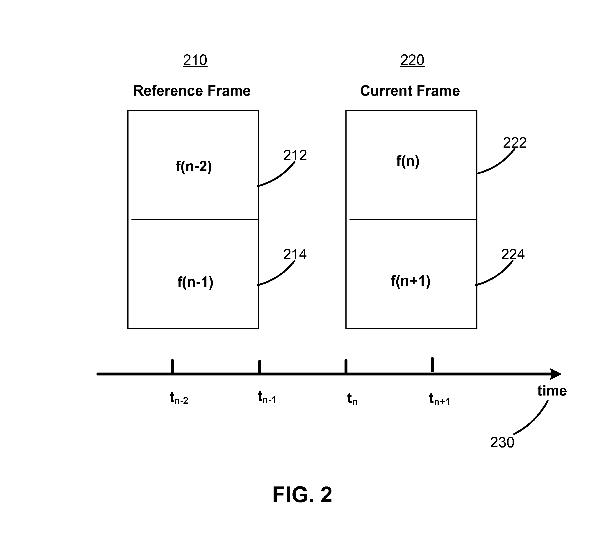
BACKGROUND[0001]1. Field of Art[0002]The disclosure generally relates to video compression, more particularly, to motion adaptive deinterlacing of a video sequence.[0003]2. Description of the Related Art[0004]Deinterlacing is a process of converting interlaced video content (e.g., ordinary TV sequences) to progressive format to be displayed on progressive devices (e.g., computers, plasmas display or projection TV). An interlaced video frame generally consists of two fields, odd / even (also called top / bottom), taken in sequence, each sequentially scanned at odd and even lines of an image sensor. Analog TV is often in interlaced format for less transmission bandwidth requirement and less perceived flicker that a similar frame rate would give using progressive scan. Modern digital displays (e.g., plasmas display TV) are inherently digital in that the display comprises discrete pixels such that the two fields of an interlaced frame need to be combined into a single frame in progressive f...

Claims


Application Information

Patent Timeline
Patent Type & Authority Patents(United States)
IPC IPC(8): H04N7/01
CPCH04N7/012H04N7/0142H04N7/0147H04N7/014H04N7/01
Inventor XIN, JUN
Owner NXP USA INC
Learn More