
System and method for moving an object

a technology of system and method, applied in the direction of magnets, conveyors, magnets, etc., can solve the problems of difficult removal, general unsafe, and difficulty in moving a first object with permanent magnets,

Active Publication Date: 2014-04-22
CORRELATED MAGNETICS RES LLC
View PDF238 Cites 28 Cited by
  • Summary
  • Abstract
  • Description
  • Claims
  • Application Information

AI Technical Summary

Benefits of technology

This patent describes a method for attaching two objects using magnetic structures. The magnetic structures have a specific alignment that creates a strong tensile force, allowing the objects to be easily attached. After attachment, the magnetic structures produce a shear force that prevents the alignment from being disturbed, even when there is no torque applied to the objects. This allows for precise and secure attachment of objects using magnetic structures.

Problems solved by technology

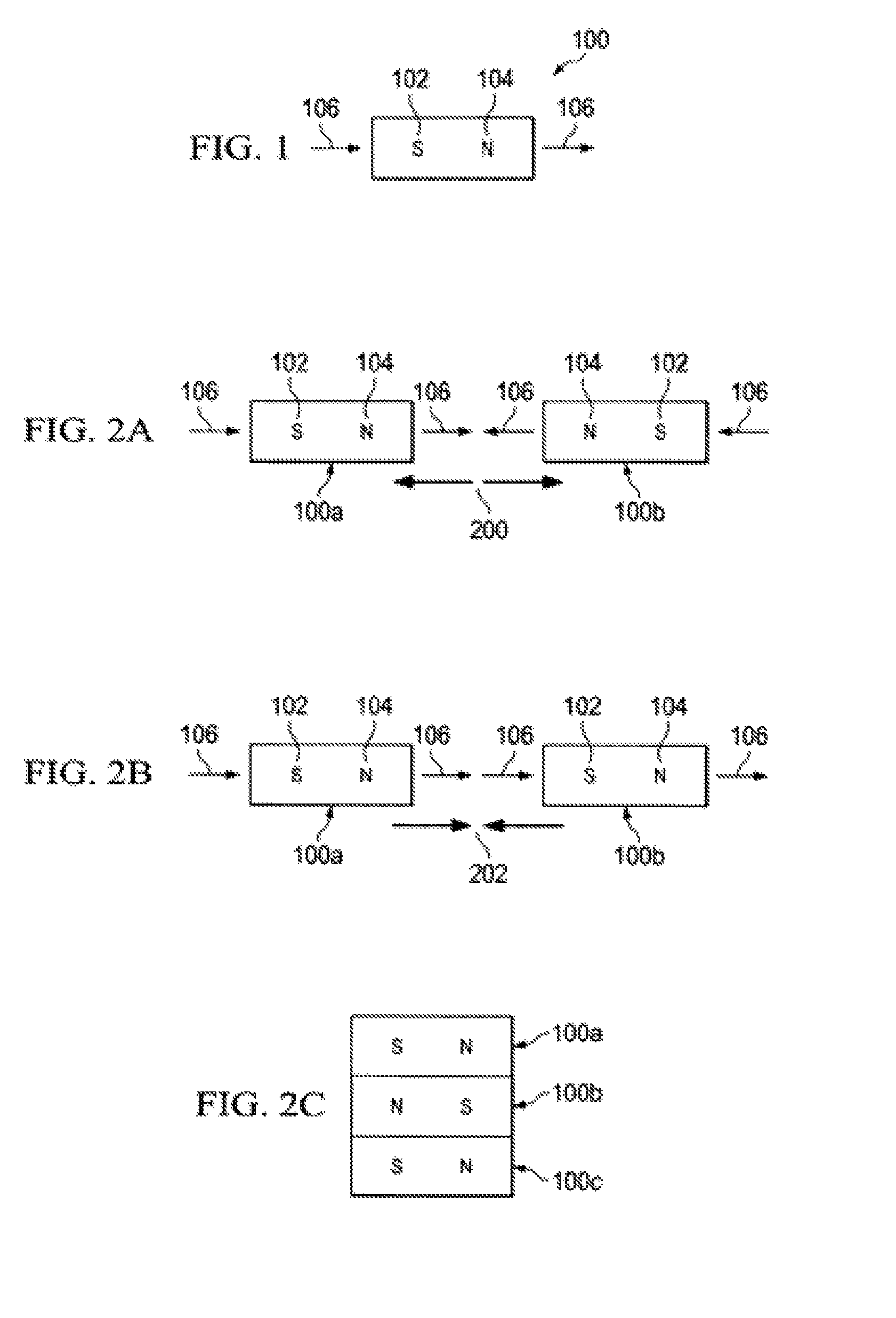
Traditionally, permanent magnets have not been a practical means for moving a first object with a second magnetically attached object for applications where the direction of movement of the first object is perpendicular to the direction of magnetization of the magnets unless an electromagnetic field is applied to the permanent magnets to effect their magnetic properties.
Because shear forces between two magnets or between a magnet and metal are low compared to tensile forces, the size of the magnet(s) required to achieve shear forces necessary to maintain attachment of two objects during such movement makes them impractical due to size, weight, cost, and safety reasons.
For example, magnets strong enough to attach a blade of a blender or food processor would need to be substantially large to maintain attachment of the blade during normal use of the appliance and would therefore be very difficult to remove, expensive, and generally unsafe in a kitchen environment where lots of metal is present such as stove tops, utensils, and even the blade itself.

Method used


Image

  • System and method for moving an object
  • System and method for moving an object
  • System and method for moving an object

Examples


Embodiment Construction

[0037]The present invention will now be described more fully in detail with reference to the accompanying drawings, in which the preferred embodiments of the invention are shown. This invention should not, however, be construed as limited to the embodiments set forth herein; rather, they are provided so that this disclosure will be thorough and complete and will fully convey the scope of the invention to those skilled in the art.

[0038]The present invention provides a system and method for moving an object. It involves coded magnetic structure techniques related to those described in U.S. patent application Ser. No. 12 / 476,952, filed Jun. 2, 2009, and U.S. Provisional Patent Application 61 / 277,214, titled “A System and Method for Contactless Attachment of Two Objects”, filed Sep. 22, 2009, and U.S. Provisional Patent Application 61 / 278,900, titled “A System and Method for Contactless Attachment of Two Objects”, filed Sep. 30, 2009, and U.S. Provisional Patent Application 61 / 278,767 t...


PUM

PropertyMeasurementUnit
magnetic structureaaaaaaaaaa
tensile forceaaaaaaaaaa
shear forceaaaaaaaaaa

Abstract

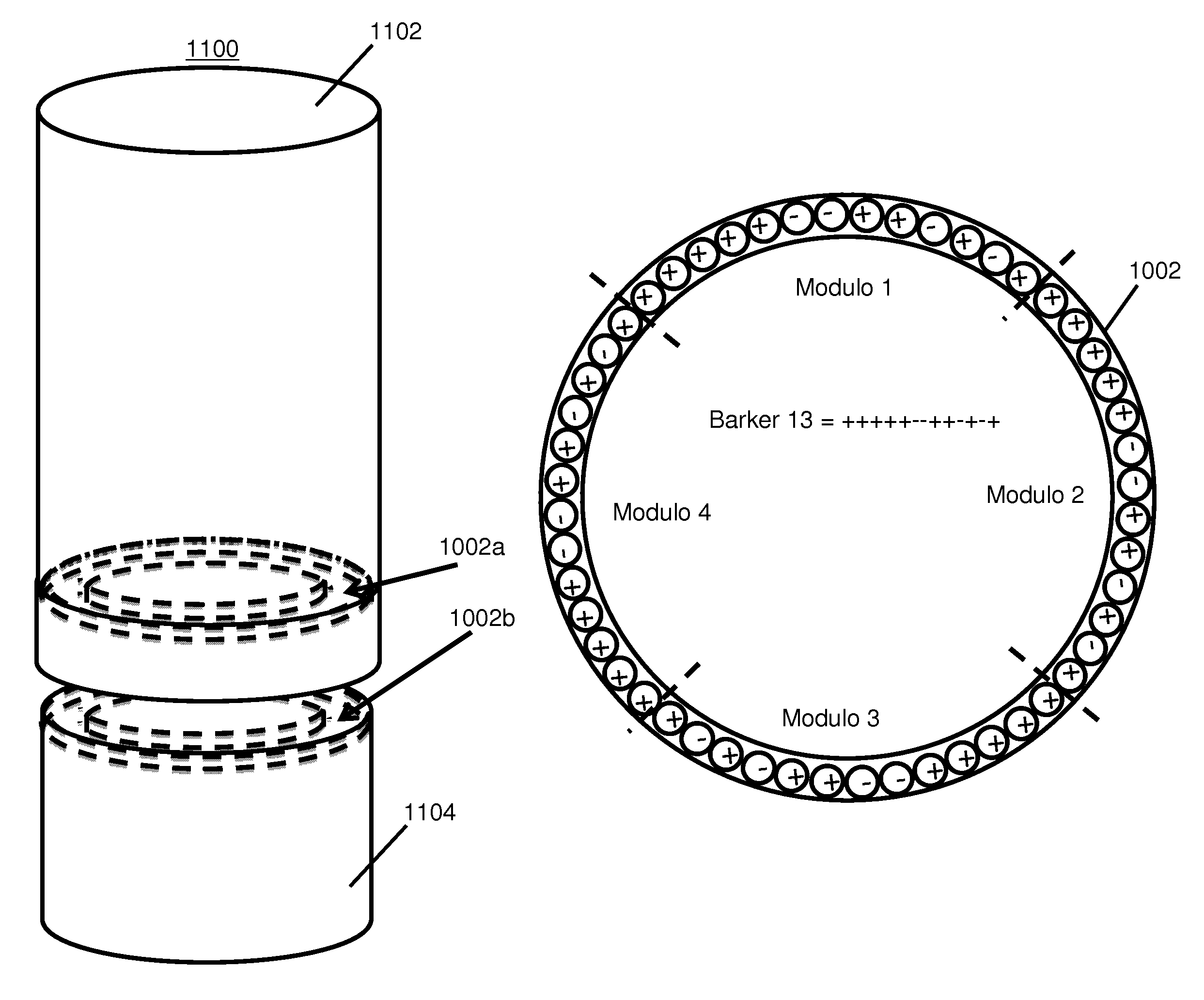
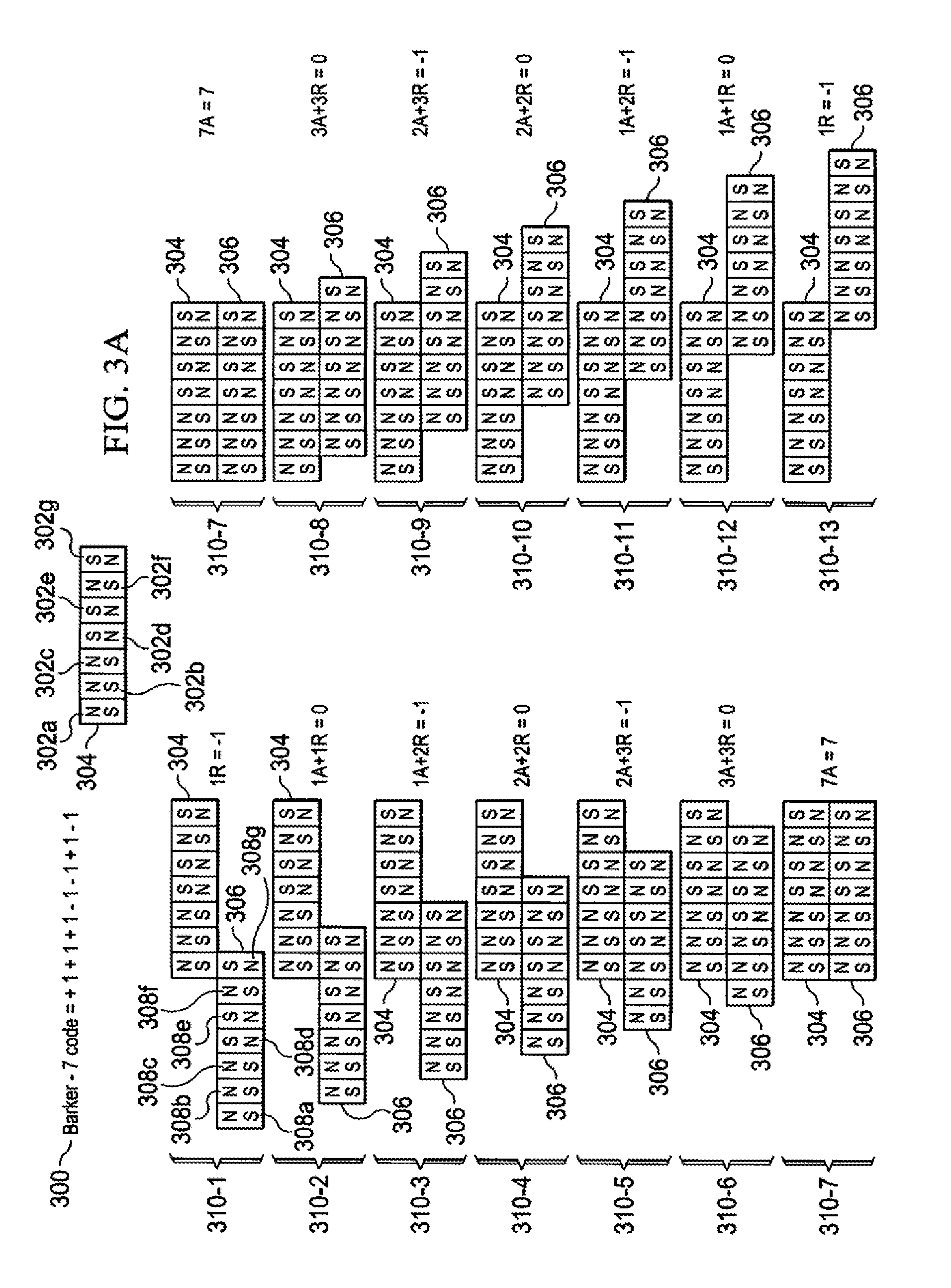
An improved system and method for moving an object includes a first correlated magnetic structure associated with a first object and a second correlated magnetic structure associated with a second object. The first and second correlated magnetic structures are complementary coded to achieve a peak attractive tensile force and a peak shear force when their code modulos are aligned thereby enabling magnetic attachment of the two objects whereby movement of one object causes movement of the other object as if the two objects were one object. Applying an amount of torque to one correlated magnetic structures greater than a torque threshold causes misalignment and decorrelation of the code modulos enabling detachment of the two objects. The number, location, and coding of the correlated magnetic structures can be selected to achieve specific torque characteristics, tensile force characteristics, and shear force characteristics.

Description

RELATED APPLICATIONS[0001]This non-provisional application claims the benefit under 35 USC 119(e) of prior provisional application 61 / 395,205 titled “A System and Method for Moving an Object” filed May 10, 2010 by Fullerton et al, which is incorporated by reference in its entirety herein.[0002]This non-provisional application is related to U.S. Pat. Nos. 7,800,471 and 7,868,721 and non-provisional application Ser. No. 12 / 476,952 titled “A field emission system and method” filed Jun. 2, 2009 by Fullerton et al, which are each incorporated by reference in their entirety herein.[0003]This non-provisional application is related to non-provisional application Ser. No. 12 / 894,837 titled “Correlated magnetic breakaway device and method” filed Sep. 30, 2010 by Williams et al, which is incorporated by reference in its entirety herein.FIELD OF THE INVENTION[0004]The present invention relates generally to a system and method for moving an object. More particularly, the present invention relate...

Claims


Application Information

Patent Timeline
Patent Type & Authority Patents(United States)
IPC IPC(8): H01F7/02
CPCB65G54/02H01F7/0247H01F7/206H01F2003/103
Inventor FULLERTON, LARRY W.ROBERTS, MARK D.
Owner CORRELATED MAGNETICS RES LLC
Learn More