
Systems and methods for source signal separation

a signal source and signal processing technology, applied in the direction of direction finders using radio waves, multi-channel direction-finding systems using radio waves, instruments, etc., can solve the problems of inability to effectively identify and isolate signal sources within a given signal, prohibitive amount of processing for conventional ss techniques,

Active Publication Date: 2014-04-08
XMOS INC
View PDF4 Cites 82 Cited by
  • Summary
  • Abstract
  • Description
  • Claims
  • Application Information

AI Technical Summary

Benefits of technology

This patent describes methods for processing signals to extract information about the underlying signals. One method involves creating two windows of the signal, one to capture the beginning of the signal and another to capture the end of the signal. The windows are then converted to a frequency domain and a tracking algorithm identifies one or more peaks in the signal. This algorithm helps to determine the modulation of the peaks and create a mathematical representation of the original signal. Another method involves creating a model of the signal using a combination of stable, frequency modulating, and amplitude modulating oscillators. This model is then used to remove the peaks from the original signal until a desired level of accuracy is achieved. The parameters of the oscillators are then encoded and stored along with the residual signal, allowing for a lossless representation of the original signal. These methods have been tested and shown to provide accurate and reliable results for signal processing applications.

Problems solved by technology

Conventional SS techniques typically require prohibitive amounts of processing to achieve real or near real time performance and are thus far quite often incapable of effectively identifying and isolating signal sources within a given signal.

Method used


Image

  • Systems and methods for source signal separation
  • Systems and methods for source signal separation
  • Systems and methods for source signal separation

Examples


Embodiment Construction

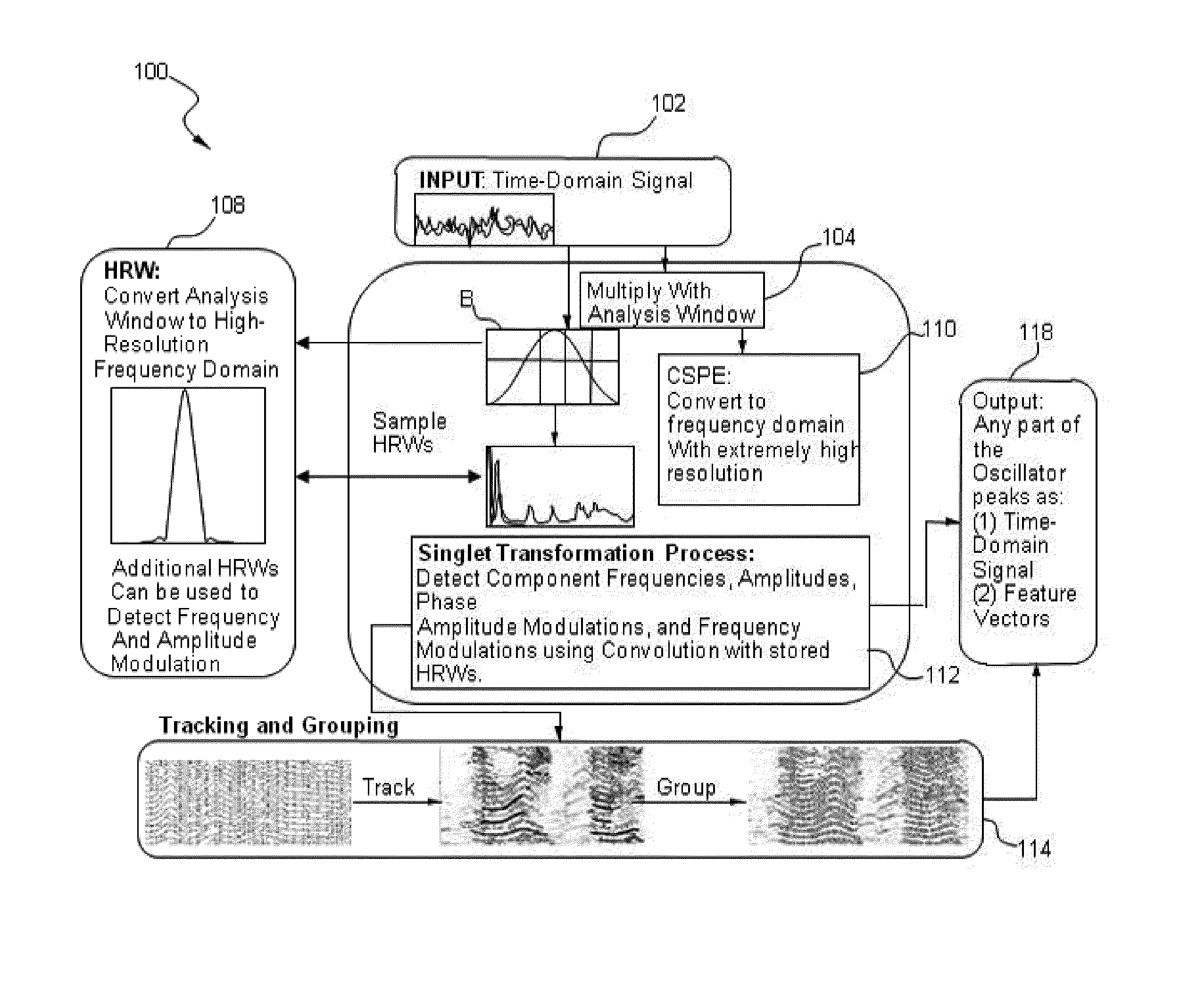
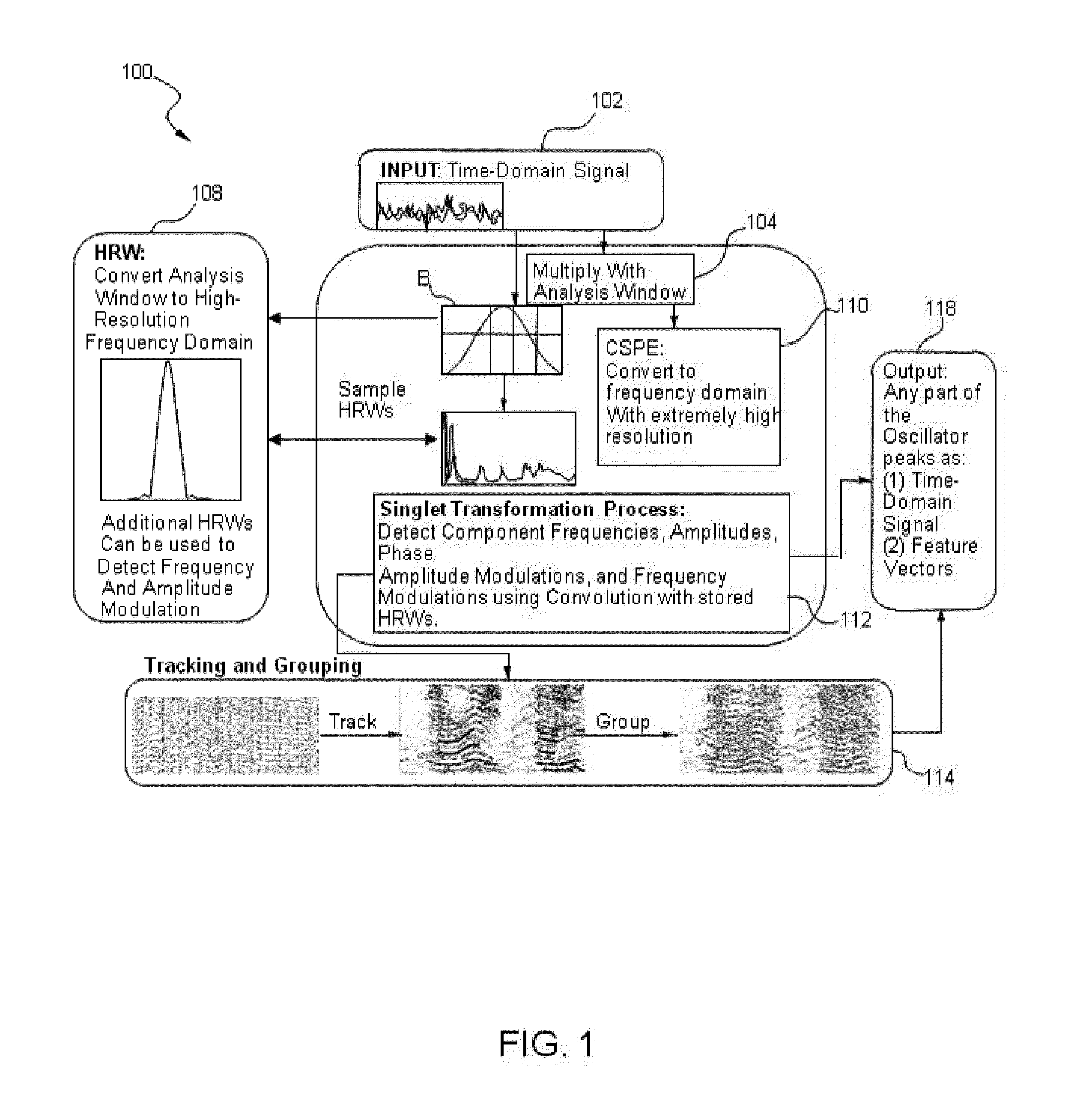
[0071]FIG. 1 illustrates an exemplary and non-limiting embodiment of a method 100 for source signal separation. In an example, a representative input signal may be a source signal (SS) including an audio signal / sound as an input to the system such that the SS is a source agnostic and may be used with respect to any type of source signal. Other representative input signals may include but are not limited to ambient sound, audio, video, speech, image, communication, geophysical, SONAR, RADAR, thermal, optical / light, medical, and musical signals. The method 100 may include one or more steps that may be used in combination or in part to analyze the SS, separate the SS into its constituent elements, and then reconstitute the SS signal in whole or in part.

[0072]As shown in FIG. 1, the method 100 may be configured to select a signal at step 102 so as to process the signal for the signal separation. In an example, contiguous samples (referred to herein as “windows” or “sample windows” that ...


PUM


Abstract

A method of processing a signal, including taking a signal formed from a plurality of source signal emitters and expressed in an original domain, decomposing the signal into a mathematical representation of a plurality of constituent elements in an alternate domain, analyzing the plurality of constituent elements to associate at least a subset of the constituent elements with at least one of the plurality of source signal emitters, separating at least a subset of the constituent elements based on the association and reconstituting at least a subset of constituent elements to produce an output signal in at least one of the original domain, the alternate domain and another domain.

Description

CROSS-REFERENCE TO RELATED APPLICATIONS[0001]This application claims the benefit of U.S. provisional patent application Ser. No. 61 / 749,606 filed Jan. 7, 2013, U.S. provisional patent application Ser. No. 61 / 785,029 filed Mar. 14, 2013, and U.S. provisional patent application Ser. No. 61 / 642,805 filed May 4, 2012 all of which are hereby incorporated by reference in their entirety.BACKGROUND[0002]1. Field of the Invention[0003]The present invention relates to methods and systems for signal processing and, more specifically, to methods and systems for separating a signal into different components.[0004]2. Description of the Related Art[0005]Signal separation (SS) is a separation of any digital signal originating from a source into its individual constituent elements, such that those elements may be deconstructed, isolated, extracted, enhanced, or reconstituted in isolation, in part, or in whole. SS may be performed on any form of data including auditory data and / or visual data or imag...

Claims


Application Information

Patent Timeline
Patent Type & Authority Patents(United States)
IPC IPC(8): G10L21/00G16B50/30
CPCH04R3/00G10L21/0272G10L15/26G10L25/18G10L13/02G01S13/723G01S13/88G01S3/74G01S3/8006G06F16/636G16B50/00G01S7/2883G01S7/288G16B50/30G01S13/89G01S3/02G10L15/02G10L15/14G10L2015/025
Inventor SHORT, KEVIN M.HONE, BRIAN T.
Owner XMOS INC
Learn More