Eureka AIR delivers breakthrough ideas for toughest innovation challenges, trusted by R&D personnel around the world.

Diaphragm for an electropneumatic horn system

a diaphragm and electropneumatic technology, applied in the field of electric horn systems, can solve problems such as negative affecting the sound emanating from the acoustic chamber, and achieve the effects of preventing unintended separation, and improving the reliability of the electric horn system

Active Publication Date: 2014-04-01
WOLO MFG
View PDF52 Cites 2 Cited by
  • Summary
  • Abstract
  • Description
  • Claims
  • Application Information

AI Technical Summary

Benefits of technology

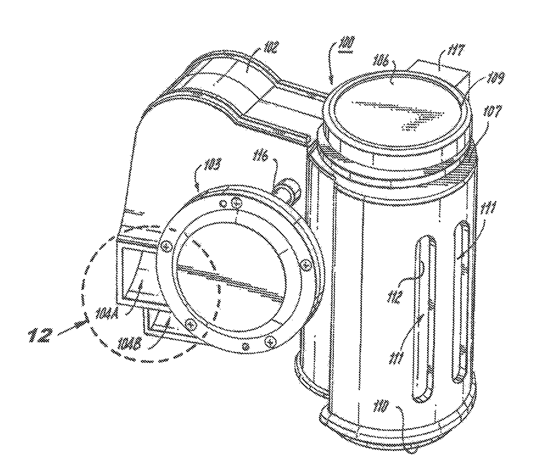
[0015]The present invention relates to an improved diaphragm or sound wave generator system for an electric horn system that includes a monolithic rigid housing member having a receiving opening for fixably housing, in an non-removable and secure manner following assembly, a compressor member, thereby preventing unintended separation and improving a reliability of the electric horn system. An acoustic sound wave generator includes an acoustic duct chambering system associated throughout with the monolithic rigid housing member. The acoustic sound wave generator receives compressed air from the compressor member to produce sound and propagate the same externally. A horn mounting system enables ready attachment of the system to a consumer-desired surface; either mechanically, magnetically, adhesively or via any other known attachment or mounting system. The present invention also relates to an electric horn system that allows permanent and irremovable attachment between the monolithic rigid housing member and the compressor member via a series of one-way attachment features preventing unintended separation.
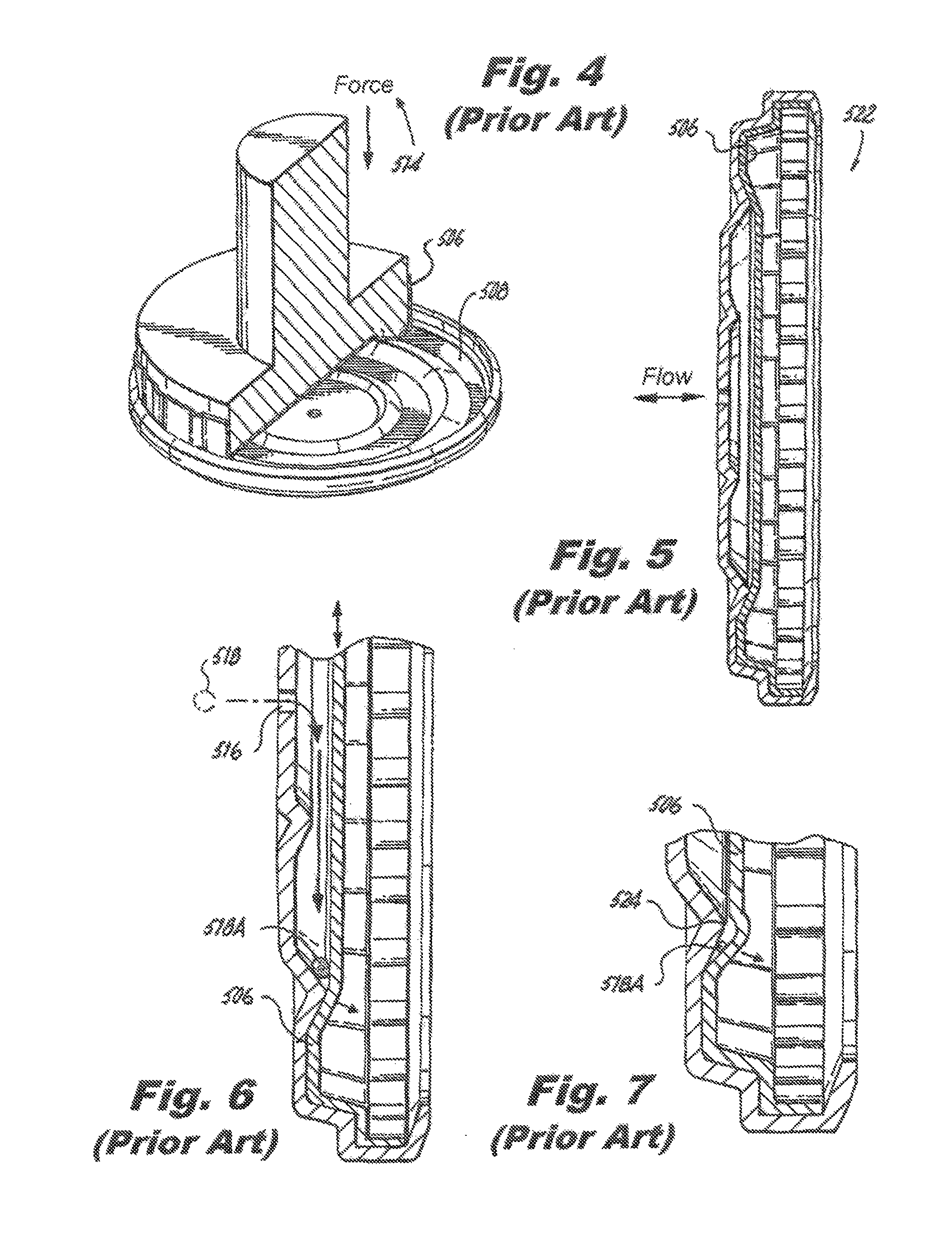
[0016]According to the preferred embodiment of the present invention there is provided an electropneumatic acoustic horn assembly, comprising: an electric compressor unit having at least a compressor air inlet and a compressor air outlet for the supply of compressed air, a sound wave generator system substantially housed in a monolithic housing assembly, the sound wave generator system comprising: at least one acoustic chamber having an opening for the introduction of the pressurized air, a membrane member provided with an opening for sound generation and at least one acoustic duct housed in the monolithic housing assembly and communicating between the at least one acoustic chamber and at least one horn outlet to propagate the sound generated by the membrane member outside the horn, air channeling means for communicating between the compressor air outlet of the electric compressor unit and the opening of the at least one acoustic chamber, means for permanently fixing the electric compressor unit in the monolithic housing assembly of the sound wave generator system, whereby the means for irremovably fixing prevents removal of the electric compressor unit and improves operational reliability of the assembly. Importantly, according to the preferred embodiment, the acoustic chamber is comprised of a substantially round and rigid membrane member removably affixed with lateral seal between an outer housing member and an inner housing member attached to the horn assembly. In other words, the membrane member is affixed within the diaphragm without the need to deform the membrane, and thus minimizes or even prevents the potential for deformities caused by unwanted particles entering the sound chamber.
[0018]According to another embodiment of the present invention there is provided an electropneumatic acoustic horn assembly, wherein diaphragm includes means for minimizing at least one of a debris and a water entry during a use of the assembly, and the means for minimizing includes at least one selected from a group comprising: an opening seal, at least one flexible louver member, at least one flexible shield member, and at least one of a woven and a metal mesh, whereby the at least one minimizing means enables a release of sound from the horn while minimizing entry of debris and water into the monolithic housing assembly.
[0019]According to another embodiment of the present invention there is provided an electropneumatic acoustic horn assembly, comprising: a cylindrical electric compressor unit having at least a compressor air inlet and a compressor air outlet for the supply of compressed air, and a first and opposing second end, a sound wave generator system substantially housed in a monolithic housing assembly, the monolithic housing assembly having a monolithic compressor housing portion having a cylindrical receiving opening, the sound wave generator system comprising: at least one acoustic chamber having an opening for the introduction of the pressurized air, a membrane member provided with an opening for sound generation and at least one acoustic duct housed in the monolithic housing assembly and communicating between the at least one acoustic chamber and at least one horn outlet to propagate the sound generated by the membrane member outside the horn, air channeling means for communicating between the compressor air outlet of the electric compressor unit and the opening of the at least one acoustic chamber, means for permanently fixing the electric compressor unit in the monolithic housing assembly of the sound wave generator system, whereby the means for irremovably fixing prevents removal of the electric compressor unit and improves operational reliability of the assembly.
[0020]Another aspect of the present invention is to provide an improved electropneumatic horn system operable at increased weather, environmental, and temperature extremes.

Problems solved by technology

Deformities such as this negatively affect the sound emanating from the acoustic chamber.

Method used


Image

  • Diaphragm for an electropneumatic horn system
  • Diaphragm for an electropneumatic horn system
  • Diaphragm for an electropneumatic horn system

Examples


Embodiment Construction

[0036]As required, a detailed illustrative embodiment of the present invention is disclosed herein. However, techniques, systems, compositions and operating structures in accordance with the present invention may be embodied in a wide variety of sizes, shapes, forms and modes, some of which may be quite different from those in the disclosed embodiment. Consequently, the specific structural and functional details disclosed herein are merely representative, yet in that regard, they are deemed to afford the best embodiment for purposes of disclosure and to provide a basis for the claims herein which define the scope of the present invention. Applicants hereby incorporate herein again by reference thereto the entire disclosure of their application Ser. No. 12 / 183,826, filed Jul. 31, 2008, now U.S. Pat. No. 7,802,535, the entire disclosure of their application Ser. No. 12 / 332,868, filed Dec. 11, 2008, now U.S. Pat. No. 7,712,430, the entire disclosure of their application Ser. No. 12 / 732...


PUM


Abstract

The invention relates to an improved diaphragm securing mechanism in a sound wave generator system for an electric horn system that includes a monolithic rigid housing member having a receiving opening for fixably housing, in an non-removable and secure manner following assembly, a compressor member, thereby preventing unintended separation and improving a reliability of the electric horn system.

Description

CROSS REFERENCE TO RELATED APPLICATIONS[0001]This application claims priority from U.S. Ser. No. 29 / 402,821 filed Sep. 28, 2011, the entire contents of which are incorporated herein by reference. This application also incorporates herein by reference the entire disclosure of application U.S. Ser. No. 12 / 183,826, filed Jul. 31, 2008, now U.S. Pat. No. 7,802,535, the entire disclosure of application Ser. No. 12 / 332,868, filed Dec. 11, 2008, now U.S. Pat. No. 7,712,430, the entire disclosure of application Ser. No. 12 / 732,367, filed Mar. 26, 2010, now U.S. Pat. No. 7,938,078.FIGURE SELECTED FOR PUBLICATION[0002]FIG. 9BACKGROUND OF THE INVENTION[0003]1. Field of the Invention[0004]The present invention relates to an electric horn system. More specifically, the present invention relates to an improved diaphragm system for an electropneumatic horn system.[0005]2. Description of the Related Art[0006]The related art involves generally electric and electropneumatic horn constructions and sys...

Claims


Application Information

Patent Timeline
Patent Type & Authority Patents(United States)
IPC IPC(8): G10K9/04
CPCH04R1/023H04R1/30H04R2499/13G10K9/04
Inventor SOLOW, STANLEY
Owner WOLO MFG
Why Eureka
Eureka Blog
Learn More