Air cleaner device

a technology of air cleaner and clamping device, which is applied in the direction of filtration separation, auxillary pretreatment, separation process, etc., can solve the problems of large number of engaging parts and clamping that interfere with efforts to reduce achieve the effect of reducing the number of component parts, avoiding time-consuming procedures, and being easy to attach and remov

Active Publication Date: 2014-03-25
HONDA MOTOR CO LTD
View PDF16 Cites 3 Cited by
  • Summary
  • Abstract
  • Description
  • Claims
  • Application Information

AI Technical Summary

Benefits of technology

[0006]It is an object of the present invention to provide an air cleaner device whereby the number of component parts is reduced and the filter element can be maintained and inspected without a time-consuming procedure.
[0008]In this manner, the support part is thus provided to the cleaner case, while the fitting ingress is formed in the support part. The pivot is also provided to the cover, and the convex part capable of fitting in the fitting ingress is formed on the pivot. The hinge part (hinge) is also formed by the support part and the pivot by fitting of the convex part in the fitting ingress. The cleaner case and the cover are connected by the hinge part so that the cover can open and close. Consequently, the cleaner case and the cover are connected by the hinge part so as to be able to open and close, and the number of engaging members (e.g., bolts) for attaching the cover to the cleaner case can thereby be reduced. Furthermore, the support part of the hinge part is formed integrally with the cleaner case, and the pivot of the hinge part is formed integrally with the cover. The number of component parts can thereby be reduced, and a filter element can be maintained and inspected without a time-consuming procedure. By reducing the number of engaging members for attaching the cover to the cleaner case, the cover 65 can easily be attached and detached in a confined space.
[0009]Preferably, the cleaner case comprises an elastically deformable seal member for supporting an entire perimeter of the filter element; the cover having a projection provided so as to be able to compress the entire perimeter of the seal member; and engaging parts provided on an opposite side of the cover from the hinge part, the engaging parts being capable of engaging with the cleaner case; and the projection being formed so as to have a large protrusion dimension in middle parts thereof between the hinge part and the engaging parts within a peripheral wall of the cover. In a state in which the engaging parts of the cover are attached to the cleaner case by the engaging members (e.g., bolts), the seal part can be reliably compressed at the middle parts (i.e., the middle parts of the cover) of the projection. The state of compression of the seal part by the projection (i.e., the cover) can thereby be suitably maintained throughout the entire perimeter of the seal part.
[0010]Desirably, the cover has an opening provided in the pivot of the cover; and in a state in which the cover is attached to the cleaner case, the seal member for supporting the filter element can be exposed to the outside through the opening. The seal part exposed in the opening is thus visible from the outside (i.e., the outside of the cover). The installation state of the seal part (i.e., the filter element) can thereby be easily confirmed when the cover is attached to the cleaner case, and installation of the seal part can be facilitated.

Problems solved by technology

In order for the case cover to be attached merely by engaging the clamps with the engaging parts, the plurality of engaging parts must be provided throughout the entire perimeter of the case, and the plurality of clamps must be provided throughout the entire perimeter of the case cover, as in the air cleaner device disclosed in JP 2003-184669 A. The need for a large number of engaging parts and clamps interferes with efforts to reduce the number of component parts.

Method used


Image

  • Air cleaner device
  • Air cleaner device
  • Air cleaner device

Examples


Embodiment Construction

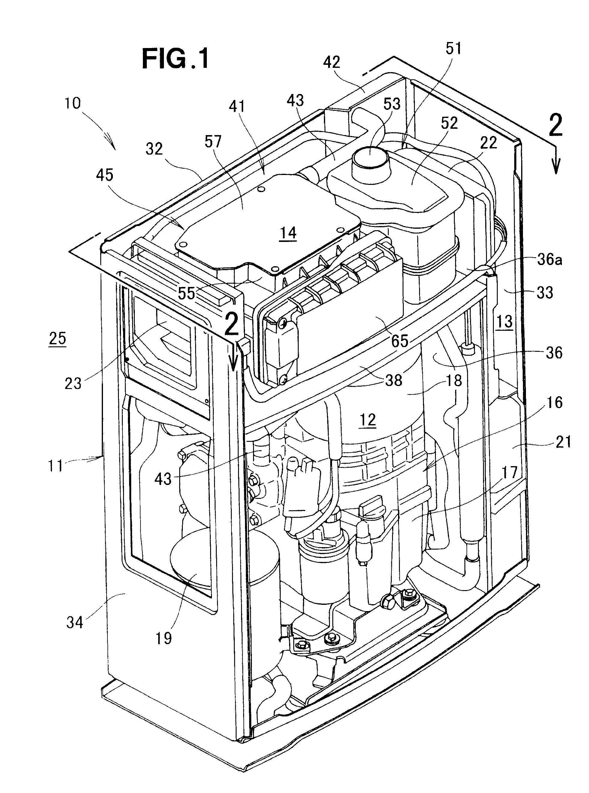
[0030]An air cleaner device 45 according to the present embodiment is used in a cogeneration apparatus 10.

[0031]As shown in FIG. 1, the cogeneration apparatus 10 is a combined heat and power apparatus provided with a cogeneration case (housing) 11 that is partitioned into a generator housing section 12 and an electrical component housing section 13; an engine (motor) 16 housed in a bottom part of the generator housing section 12; a generator 18 provided to a top part of an engine body 17; a heat exchanger 19 provided beside the engine body 17; a first control unit 21 housed in a bottom part of the electrical component housing section 13; and a power converter 22 housed in a top part of the electrical component housing section 13.

[0032]The cogeneration case 11 is formed having a substantially rectangular shape by a front panel, a rear panel 32, a left side panel 33, a right side panel 34, and a roof panel. The front panel and the roof panel are not shown in the drawings. A dividing w...


PUM

PropertyMeasurementUnit
perimeteraaaaaaaaaa
compressaaaaaaaaaa
protrusion dimensionaaaaaaaaaa

Abstract

An air cleaner device whereby the number of component parts is reduced and the filter element can be maintained and inspected without a time-consuming procedure. The air cleaner device includes: a support part provided to a cleaner case and having a fitting ingress at a region on the opposite side thereof from the cover; and a pivot provided to the cover and having a convex part capable of fitting in the fitting ingress of the support part. A hinge part for connecting the cover to the cleaner case so that the cover can open and close is formed by the support part and the pivot by fitting of the convex part in the fitting ingress.

Description

FIELD OF THE INVENTION[0001]The present invention relates to an air cleaner device wherein a filter element is provided partway in an air intake passage communicating with a motor and air drawn into the air intake passage is cleaned by the filter element and introduced into the motor.BACKGROUND OF THE INVENTION[0002]Known air cleaner devices include the air cleaner device disclosed in Japanese Patent Application Laid-Open Publication No. 2003-184669 (JP 2003-184669 A), for example, in which a filter element is housed in a case, a plurality of engaging parts is provided to the case in which the filter element is housed, and a plurality of clamps capable of engaging with the plurality of engaging parts is provided to a case cover.[0003]In this air cleaner device, the case cover is attached to the case by engaging the plurality of clamps with the respective plurality of engaging parts. The case cover is removed from the case by disengaging the plurality of clamps from the plurality of ...

Claims


Application Information

Patent Timeline
Patent Type & Authority Patents(United States)
IPC IPC(8): B01D51/00B01D59/00B01D49/00B01D39/00B01D59/50B01D45/00B01D46/00B01D57/00B01D53/00B01D50/00
CPCB01D46/10B01D46/0005F02M35/0203F02M35/02416
Inventor USHIYAMA, HIDEYUKINAOI, ATSUMU
Owner HONDA MOTOR CO LTD
Why Eureka
Try Eureka