
Direct detection Doppler LIDAR method and direction detection Doppler LIDAR device

a technology of doppler lidar and direct detection, which is applied in the direction of devices using optical means, instruments, reradiation, etc., can solve the problems of high cost, difficult to achieve, and high complexity of received signals, and achieve the effect of increasing the dynamic range of a doppler lidar system

Active Publication Date: 2014-03-18
EADS DEUT GMBH
View PDF46 Cites 26 Cited by
  • Summary
  • Abstract
  • Description
  • Claims
  • Application Information

AI Technical Summary

Benefits of technology

This patent describes a method and apparatus for improving the detection of signals from a Doppler LIDAR system. The invention allows for the detection of signals with a wide dynamic range using a detector with a narrower dynamic range. By controlling the laser source and the detector, the system can measure objects at high speeds using a direct reception technique. The method is simple to implement and can increase the accuracy of LIDAR measurements. The technical effects of this invention include improved dynamic range and accuracy in measuring speeds and objects using a direct reception LIDAR system.

Problems solved by technology

Attenuation of the received signal, by way of example using electrooptical modulators, is highly complex, expensive and is difficult to achieve because of the normally large apertures for CCD chips.

Method used


Image

  • Direct detection Doppler LIDAR method and direction detection Doppler LIDAR device
  • Direct detection Doppler LIDAR method and direction detection Doppler LIDAR device
  • Direct detection Doppler LIDAR method and direction detection Doppler LIDAR device

Examples


Embodiment Construction

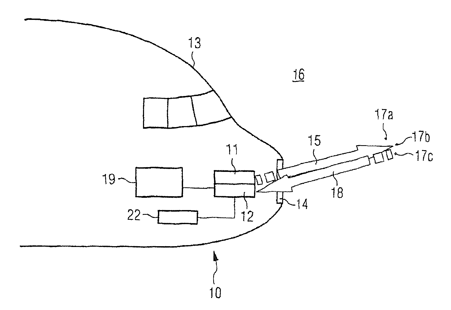
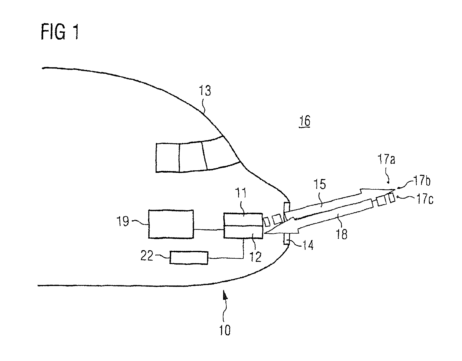
[0043]FIG. 1 shows a schematic illustration of a direct reception Doppler LIDAR apparatus 10. The direct reception Doppler LIDAR apparatus 10 in the illustrated example is installed in an aircraft, illustrated using the example of an airplane 13.

[0044]The direct reception Doppler LIDAR apparatus 10 has a laser source 11 with a relatively narrow bandwidth (single-frequency operation, typical line width several MHz). The light from the laser source 11—transmitted laser beam 15—is transmitted through a window 14 into the atmosphere 16. In the atmosphere 16, the light from the laser source 11 is elastically scattered on particles 17a, 17b, 17c, . . . in the air, in the case illustrated by way of example here. The scattered light 18 is recorded by a detector arrangement 12. The relative speed is determined in an evaluation device 19 from the Doppler shift of the scattered light 18, which has been scattered back on the scatter particles 17a, 17b, 17c, which move relative to the direct rec...


PUM


Abstract

The invention relates to a method for Doppler light detection and ranging (LIDAR) measurement of speeds. A laser beam is directed at the medium to be measured, and radiation which is then emitted by the medium is measured by a detector. In order to allow better control of the dynamic range of a direct reception Doppler LIDAR apparatus, a multiplicity of laser pulses can be transmitted per measurement, and a multiplicity of laser pulses can be received by the detector per measurement. A direct reception Doppler LIDAR apparatus can be suitable for carrying out the method.

Description

CROSS-REFERENCE TO RELATED APPLICATIONS[0001]This U.S. National stage application claims priority under 35 U.S.C. §119(a) to German Patent Application No. 10 2008 031 682.2, filed in Germany on Jul. 4, 2008, the entire contents of which are hereby incorporated herein by reference.BACKGROUND[0002]1. Field of the Invention[0003]The invention relates to a method for Doppler LIDAR measurement of speeds by means of direct reception, and to an apparatus for carrying out the method.[0004]LIDAR is short for “light detection and ranging” and is a method, which is closely related to radar (“radio-wave detection and ranging”), for range and speed measurement, as well as for remote measurement of atmospheric parameters. However, laser beams are used instead of radio waves, as in the case of radar.[0005]One example of a Doppler LIDAR apparatus and of a method which can be carried out using it for measuring wind speeds is known from EP1756620 B1, US 20080117433 A1 or US 2006262324 A1.[0006]In the...

Claims


Application Information

Patent Timeline
Patent Type & Authority Patents(United States)
IPC IPC(8): G01P3/36
CPCG01S17/95Y02A90/10
Inventor SCHMITT, NIKOLAUSREHM, WOLFGANGPISTNER, THOMAS
Owner EADS DEUT GMBH
Learn More