
Respiratory apparatus

a technology of respiratory apparatus and stent, which is applied in the direction of valve operating means/release devices, machines/engines, liquid fuel engines, etc., can solve the problems of affecting the quality of patient's sleep, so as to enhance the treatment delivery

Active Publication Date: 2014-03-11
RESMED LTD
View PDF59 Cites 17 Cited by
  • Summary
  • Abstract
  • Description
  • Claims
  • Application Information

AI Technical Summary

Benefits of technology

The patent text describes a new mask system for a CPAP device that can be integrated into a single wearable device. This system has several advantages including improved treatment delivery, streamlined design for increased patient freedom of movement, reduced size of the blower for lower power requirements, and a less obtrusive and more intuitive design for the patient. The flow generator in the system may also be reduced in size and operate on a rechargeable power supply for the entirety of the patient's sleep cycle. The new system may also generate less noise and be more efficient. Overall, the patent text outlines a new approach to create a more effective and comfortable CPAP device for patients with sleep apnea.

Problems solved by technology

Most OSA suffers do not remember these arousals, however each arousal places extra strain on a patient's heart and destroys the quality of their sleep.
The patient interface and tube tend to be bulky, and the tube may be rather long, e.g. from about 2-3 m in length.
The headgear used to maintain the patient interface in contact with the patient's face may also be bulky and / or complicated to correctly put on and / or adjust.
These factors may make a patient reluctant to start CPAP therapy.
These factors may also make it difficult for the patient to find a comfortable sleeping position.
During sleep, the patient may change position, and the tube may exert a force, i.e. tube drag, on the patient interface which may disrupt the seal between the patient interface and the patient's face.
This may result in a leak in the patient interface, which reduces the efficacy of the treatment.
Leakage from the patient interface may also irritate the patient, or the patient's sleeping partner, thus further damaging the quality of the patient's sleep.
Patients using a typical CPAP apparatus for therapy may also find it difficult to travel with the apparatus.
The flow generator, tube, and mask may be difficult to pack in luggage, and may take up a lot of room within the luggage.
The patient may also find it difficult to use the apparatus away from home as the flow generator typically includes a power cord that must be plugged into a power source, e.g. an AC wall socket, which may not be accessible, or available, at the location the patient is visiting.

Method used


Image

  • Respiratory apparatus
  • Respiratory apparatus
  • Respiratory apparatus

Examples


first embodiment

Respiratory Apparatus First Embodiment

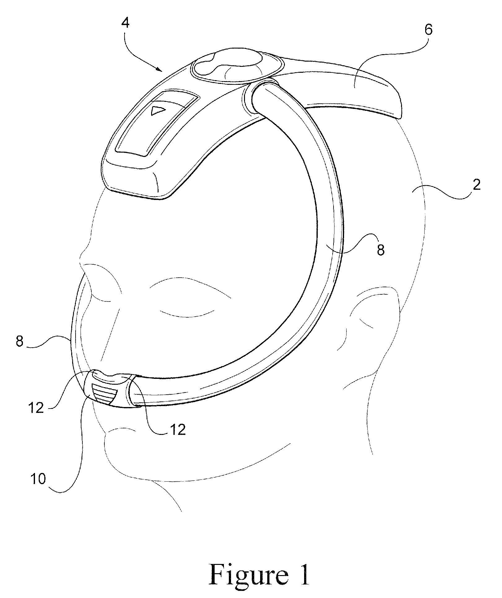
[0041]Referring to FIG. 1, a respiratory apparatus for delivering a flow of pressurized breathable gas to a patient 2, for example to treat SBD, such as OSA, comprises a flow generator 4 to generate the flow of pressurized breathable gas. The flow generator 4 is contained in a flow generator housing or casing 6 that is anthropometrically configured to engage the head of the patient 2. As shown in FIG. 1, the flow generator housing 6 is configured to engage the top of the patient's head to permit the patient to sleep on the patient's side without disturbing the positioning of the flow generator housing 6. As shown in FIG. 1, the flow generator housing may have a curvature in the back to front direction of the housing, and a curvature in a lateral direction, i.e. in a direction from one side of the patient's head to the other side.

[0042]The flow generator 4 delivers a flow of pressurized breathable gas through delivery tubes or conduits 8 which ar...

second embodiment

Respiratory Apparatus Second Embodiment

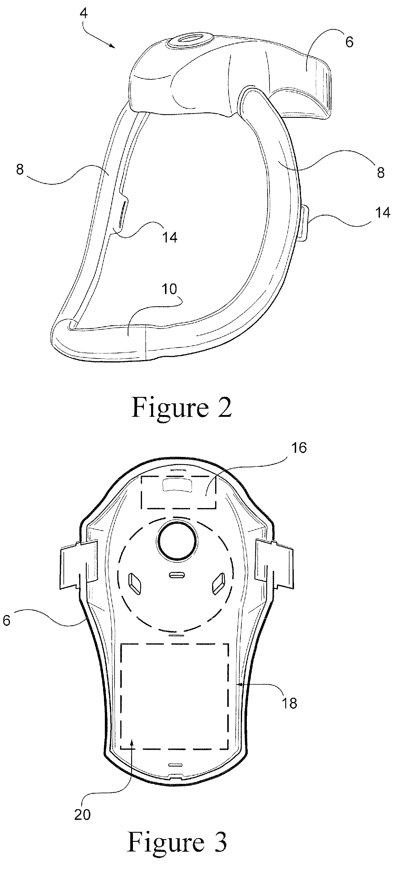
[0044]Referring to FIG. 2, a respiratory apparatus according to another sample embodiment includes strap attachment portions 14 provided on the delivery conduits 8. A strap, or headgear system, may be connected to the strap attachment portions to provide additional securement of the respiratory apparatus to the head of the patient. As shown in FIG. 2, the flow generator housing 6 may be configured to extend towards the back of the head of the patient 2, but may not extend as far forward on the head of the patient 2 as the flow generator housing 6 of the sample embodiment of FIG. 1.

[0045]Referring to FIG. 3, the flow generator housing 6 may be configured to support a voltage regulator 16, a motor controller 18 and a power source 20. The power source 20 may comprise a battery, or a plurality of batteries. For example, the battery or batteries may be configured as lithium polymer batteries having a volumetric energy density of about 250-530 Wh / L, ...

third embodiment

Respiratory Apparatus Third Embodiment

[0062]Referring to FIG. 16, a respiratory apparatus according to another sample embodiment comprises a flow generator 4 provided in a flow generator housing 6 configured to engage the head of the patient, for example the crown of the patient's head. The flow generator 4 is configured to deliver a flow of pressurized breathable gas to delivery conduits 8 which are configured to extend from the flow generator along the sides of the face of the patient to a patient interface 10. The patient interface may include nasal pillows or prongs, a nasal mask, a full face mask, or cannulae.

[0063]Power is provided to the flow generator 4 by a power supply and controller 66 that is connected to the flow generator 4 by an electrical connector 68, for example a cable. The power supply / controller 66 may be configured to be docked in a battery charger, or may include an attachment that allows for charging of the power supply and controller from a voltage source, f...


PUM


Abstract

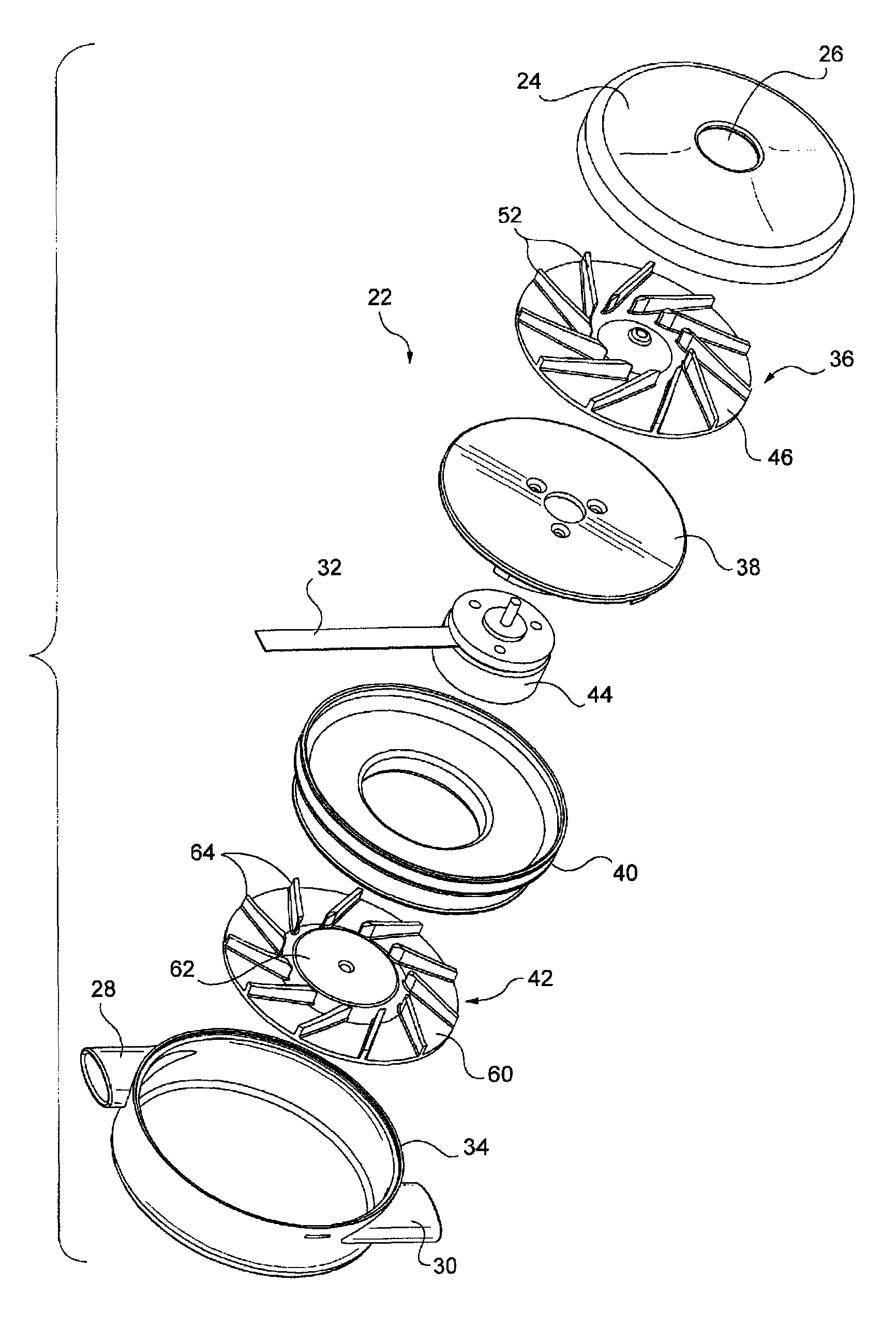
A flow generator for generating a flow of pressurized breathable gas includes a cylindrical housing and a motor supported in the housing. The motor has a shaft having a first end and a second end opposite the first end. The shaft is generally coincident with an axis of the motor. A first impeller is attached to the first end of the shaft and a second impeller is attached to the second end of the shaft. A stator directs an air flow from the first impeller back towards the motor axis. The housing includes an inlet adjacent the first end of the shaft having an inlet axis generally coincident with the motor axis and at least one outlet between the first and second impellers. The at least one outlet has an outlet axis generally tangential to the motor axis.

Description

CROSS REFERENCE TO RELATED APPLICATION[0001]This application claims priority to U.S. Application 61 / 024,993, filed Jan. 31, 2008, the entire contents of which are incorporated herein by reference.INCORPORATION BY REFERENCE[0002]The entire contents of WO 2008 / 028247 A1, are incorporated herein by reference.FIELD OF THE INVENTION[0003]The present invention relates to a respiratory apparatus for delivering a flow of pressurized breathable gas to a patient.BACKGROUND OF THE INVENTION[0004]Obstructive Sleep Apnea (OSA) is a sleep breathing disorder (SBD). For those who have OSA, when they sleep the soft tissue in their throat and airway relax and collapse thus blocking the airway and preventing airflow to the lungs. This cessation of breathing, known as an apnea, can last for up to one minute before the blood oxygen levels reach a critical point where the patient has an arousal and their airway reopens. Most OSA suffers do not remember these arousals, however each arousal places extra st...

Claims


Application Information

Patent Timeline
Patent Type & Authority Patents(United States)
IPC IPC(8): F04D25/16F04D17/12F04D17/08A61M16/00F04D25/00F04D17/00
CPCA61M2205/42A61M16/0057F04D17/164F04D29/664A61M16/0066A61M16/0694A61M16/06A61M2205/8206A61M16/0683A61M2205/8237A61M2209/086A61M16/0666A61M16/0051A61M16/0633A61M16/00A61M16/08A61M16/0816A61M16/0875F04D29/4246A61M16/021A61M2209/088F04D17/12F04D25/0673F04D27/004F04D29/281F04D29/4206
Inventor KENYON, BARTON JOHNDOHERTY, RENEE FRANCESBRAMBILLA, ENRICOKWOK, PHILIP RODNEY
Owner RESMED LTD
Learn More