
Grenade mechanism

a technology of grenade and mechanism, which is applied in the field of hand grenades, can solve the problems of grenade explosion, entire storage area could explode, and fatal injuries, and achieve the effect of preventing accidental detonation of grenad

Active Publication Date: 2014-03-04
IMI SYST LTD
View PDF10 Cites 8 Cited by
  • Summary
  • Abstract
  • Description
  • Claims
  • Application Information

AI Technical Summary

Benefits of technology

The present invention aims to provide an auxiliary safety mechanism for grenades to prevent accidental detonation. The mechanism is designed to mechanically separate the grenade's ignition portion from the explosive charge, allowing for normal use without any further activity required by the user. Additionally, the grenade's outer shell is not welded together but attached in a way that they will come apart when a bullet or shrapnel penetrate the grenade before the explosive material contained therein has a chance to explode. This ensures that the grenade's safety is not compromised during handling or use.

Problems solved by technology

If for any reason one of the pyrotechnic components are activated, unintentionally, such as by extreme heat or by penetration of a bullet or fragment it inevitably causes the grenade to explode.
Unintended explosion of a hand grenade can cause fatal injuries.
If large numbers of grenades are stored in a single or enclosed storage area and if a grenade unintentionally explodes, the entire storage area could explode and cause great damage.
The aforementioned safety consideration imposes constraints on the storage and transportation of hand grenades and puts the personnel in vicinity of hand grenades at risk.
It is also a waste of resources, which may be needed at any time.
Thus the safety mechanism is dependent on the safety lever, and any damage thereof will void this auxiliary safety mechanism.

Method used


Image

  • Grenade mechanism
  • Grenade mechanism
  • Grenade mechanism

Examples


Embodiment Construction

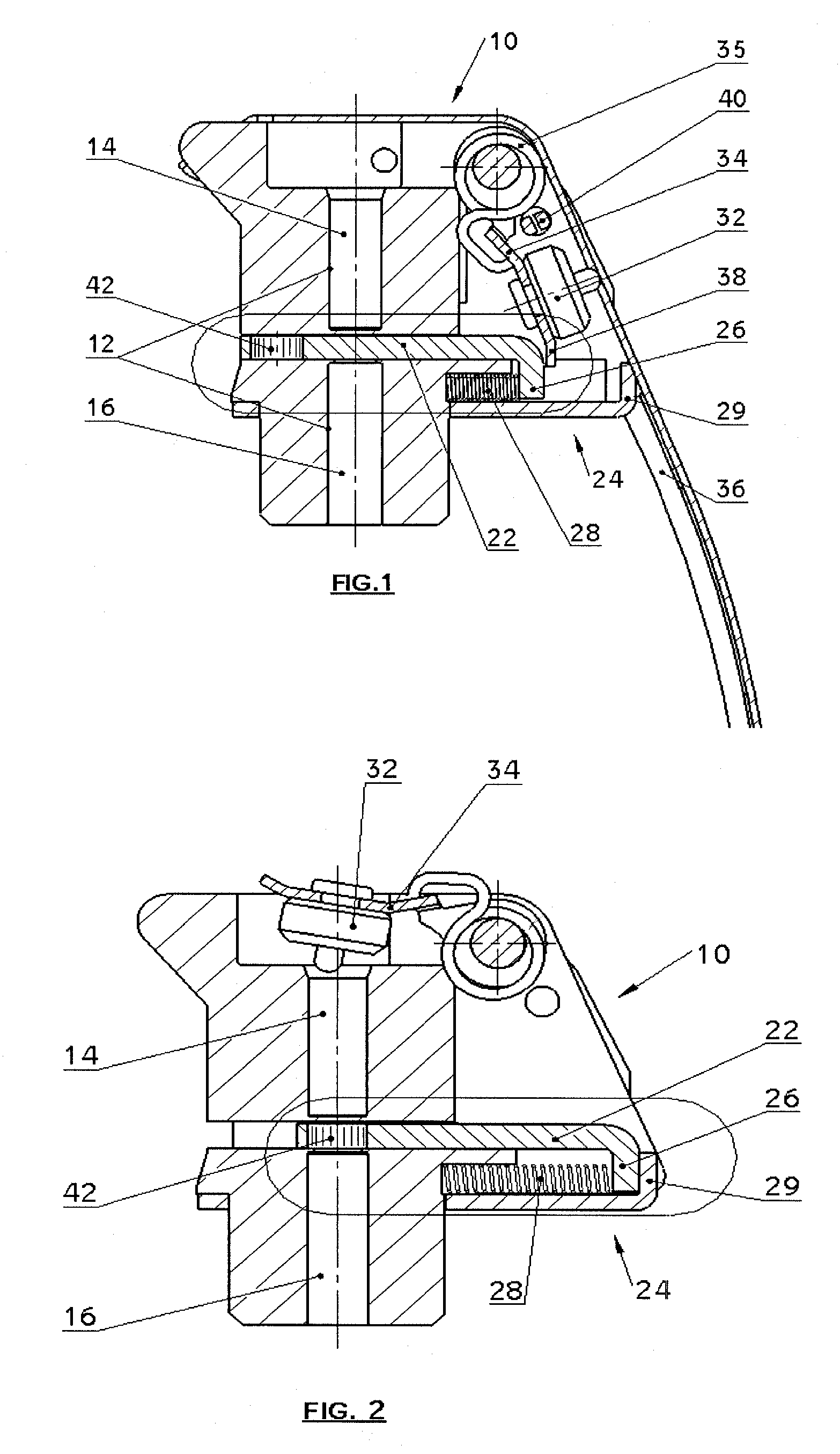
[0034]Referring first to FIGS. 1 and 2, there is shown a fuse housing 10 of a grenade with an auxiliary safety mechanism 24 in accordance with an embodiment of the present invention in a safe and armed condition, respectively. The grenade body housing a main charge is not shown.

[0035]In FIG. 1 the fuse housing 10 is shown in a safe condition and in FIG. 2 in an armed condition. The fuse housing 10 has a bore 12 containing a delay detonator 14 near its upper end and an explosive column 16 at its lower end. A striker 32 is attached to a striker lever 34 having an edge 38 is held under tension by a spring 35 and is held in its place by the safety pin 40. An auxiliary safety mechanism 24 includes the slider element 22 having at one end a relay charge 42 and at the other end a flanged edge 26. The edge 38 of the striker lever 34 presses against the end 26 of the slider element 22 compressing the slider spring 28 and pushes the slider element 22 forward traversing the explosive train sepa...


PUM


Abstract

An auxiliary safety mechanism for a grenade to prevent detonation from shockwaves, heat, fragments, etc., the grenade including a fuse housing containing a delay detonator and explosive train. In at least one embodiment, the fuse housing includes a reversible slider element interposed between the delay detonator and the rest of the explosive train to form a barrier therebetween when the grenade is in an unarmed condition, and when the slider element is withdrawn the barrier between the delay detonator and explosive train is removed leaving the grenade in an armed condition. In another embodiment, a further safety mechanism involves connecting the two sections of the housing with a weak connection that ruptures prior to the explosive contained therein reaching the critical explosive temperature / pressure.

Description

[0001]This is a Continuation Application of and claims priority under U.S.C. §120 to PCT Patent Application No. PCT / IL2010 / 001044, filed on Dec. 12, 2010, the contents of which are hereby incorporated by reference in their entirety.FIELD[0002]The present application generally relates to hand grenades, in particular to safety features with respect of the grenades.BACKGROUND[0003]In typical present day hand grenades, the outer shell of the grenade is made of serrated steel sections welded together that holds a pyrotechnic fuse mechanism, which is surrounded by a high explosive material. The grenade has a filling hole for pouring in the high explosive material.[0004]The firing mechanism is triggered by a spring-loaded striker inside the grenade. Normally, the striker is held in place by a striker lever, which is held in place by a safety pin, usually a cotter pin. The striker lever is held against the body of the grenade and when the pin is pulled out, the firing mechanism is triggered...

Claims


Application Information

Patent Timeline
IPC IPC(8): F42B27/00F42C15/21
CPCF42C15/34F42C14/02
Inventor VEKSLER, ISAR
Owner IMI SYST LTD
Learn More