
Child safety seat

A child safety seat and socket technology, which is applied to child seats, vehicle seats, special positions of vehicles, etc., can solve the problems of no accidental explosion prevention device, airbag inflation and ejection, etc., to prevent accidental explosion and protect children's safety Effect

Pending Publication Date: 2020-04-10
GOODBABY CHILD PROD CO LTD
View PDF0 Cites 0 Cited by
  • Summary
  • Abstract
  • Description
  • Claims
  • Application Information

AI Technical Summary

Problems solved by technology

However, the safety airbag system in the prior art does not have an anti-inadvertent explosion device. If the child safety seat is not used normally (such as the child does not ride, the child is placed in the process of the child safety seat, the child will fall out of the child safety seat. In the event of an impact, the airbag will still be inflated and ejected

Method used


Image

  • Child safety seat
  • Child safety seat
  • Child safety seat

Examples


Embodiment 1

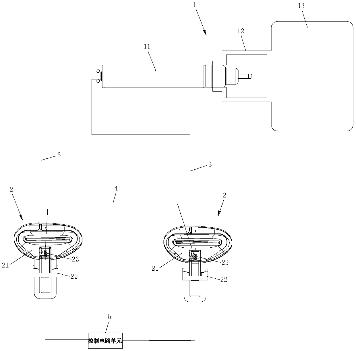
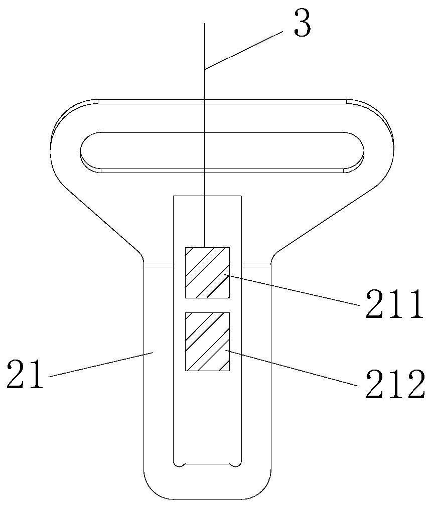
[0043] From attached figure 1 to attach Figure 10 It can be seen from the schematic diagram of the structure that the child safety seat in this embodiment includes a passive protection device 1, two controllers 2, a wire 4 connected to the two controllers 2 at both ends, and connected to the two controllers at both ends. The control circuit unit 5 connected to the device 2.

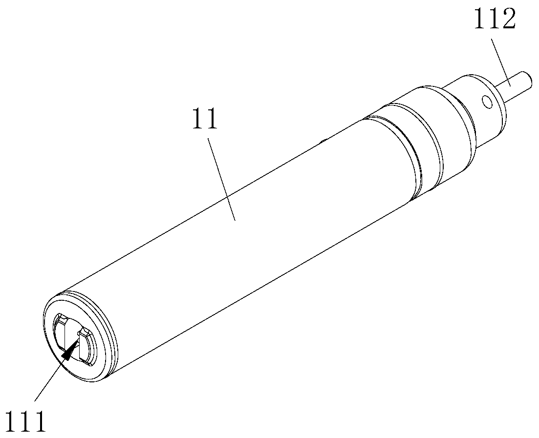
[0044] The passive protection device 1 includes a triggered device, which in this embodiment is a gas generator 11 . The passive protection device 1 has a closed state and a to-be-triggered state. In the closed state, the passive protection device 1 will not be triggered, and in the to-be-triggered state, the passive protection device 1 can be triggered. as attached figure 1 In the illustrated embodiment, the passive protection device 1 includes the above-mentioned gas generator 11 and an airbag 13 connected to the gas generator 11 through a pipe joint 12 . as attached figure 2 As shown, one end of t...

Embodiment 2

[0059] Reference attached Figure 11 to attach Figure 15 The difference between the child safety seat in this embodiment and the first embodiment mainly lies in the structure of the state switching device.

[0060] The state switching device in this embodiment includes a switch 24 arranged on the plug connector 21, and the switches 24 in the two controllers 2 are respectively connected between the two ends of the wire 4 and the corresponding connecting wire 3, and the state switching device also It includes a driving part arranged on the slider 22 and capable of opening and closing the toggle switch 24. When a certain controller 2 is in the first working state, the end of the control circuit unit 5 is separated from the plug connector 21 and disconnected. Simultaneously, the slider 22 is in the first working position, the switch 24 is closed, the wire 4 is connected to the corresponding connecting wire 3, so that the wire 4 short-circuits the gas generator 11, and when the s...


PUM


Abstract

The invention discloses a child safety seat which comprises a passive protection device, two controllers, a wire and a control circuit unit, wherein the two ends of the wire are connected with the twocontrollers respectively, and the two ends of the control circuit unit are connected with the two controllers respectively. The passive protection device comprises a triggered device, and the two ends of the triggered device are detachably connected with the two controllers respectively. Each controller has a first working state and a second working state which can be switched with each other. When the two controllers are both in the first working state, the two ends of the wire are connected with the two ends of the triggered device through the two controllers respectively, and the passive protection device is in a closed state; and when the two controllers are both in the second working state, the two controllers enable the two ends of the wire to be disconnected from the two ends of the triggered device respectively, the two ends of the control circuit unit are connected with the two ends of the triggered device through the two controllers respectively, and the passive protection device is in a to-be-triggered state.

Description

technical field [0001] The invention relates to a child safety seat. Background technique [0002] The child safety seat is used to protect children's riding safety, and includes a seat body and a restraint mechanism connected with the seat body. When an actual collision occurs, due to the inertial force caused by the powerful impact, even if restrained by the restraint mechanism (restraint belt or block) on the child safety seat, the child's body will still lean forward, so that on the one hand, it will often Due to the force of the restraint mechanism, the child's body is strongly compressed and caused injury. On the other hand, the child's body may bump into other objects in the car due to the excessive range of forward movement of the child's body, causing injury to the child. Therefore, some child car seats are equipped with airbags, which can be inflated and collided to protect children when a collision occurs. However, the safety airbag system in the prior art does ...

Claims


Application Information

Patent Timeline
Patent Type & Authority Applications(China)
IPC IPC(8): B60N2/28
CPCB60N2/2884B60N2/28
Inventor 贺新军高翔
Owner GOODBABY CHILD PROD CO LTD
Learn More