Liquid crystal display device
a display device and liquid crystal technology, applied in liquid crystal compositions, instruments, chemistry apparatus and processes, etc., can solve the problems of difficult to prevent the reverse transition sufficiently, and the reverse transition cannot be sufficiently prevented, so as to prevent the reverse transition. deterioration
- Summary
- Abstract
- Description
- Claims
- Application Information
AI Technical Summary
Benefits of technology
Problems solved by technology
Method used
Image


Examples
embodiment 1
[0146]An embodiment of the present invention is described below with reference to drawings such as FIG. 1.
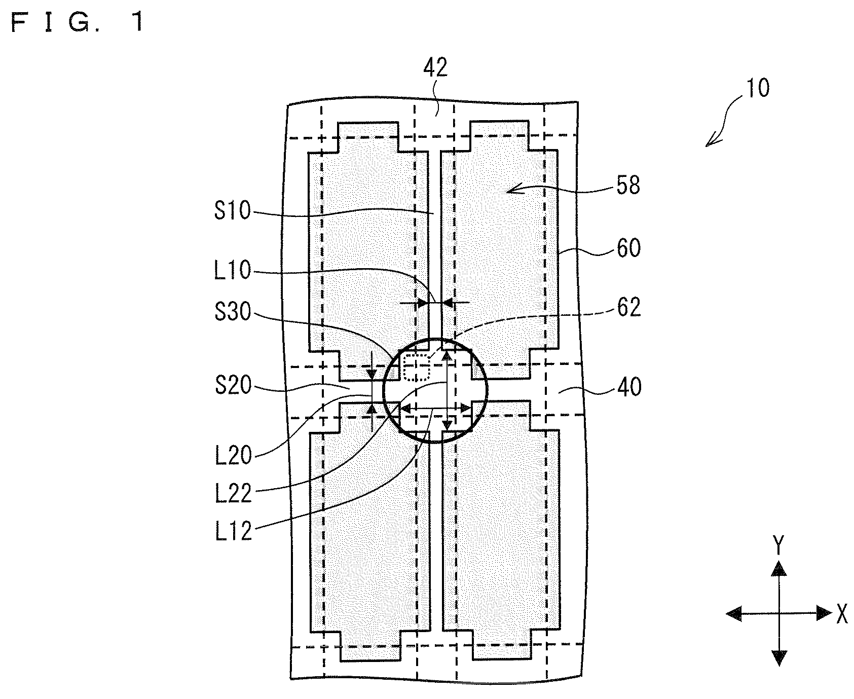
[0147]FIG. 1 is a view illustrating a shape of a pixel electrode in a liquid crystal display device of the present embodiment.
[0148]A liquid crystal display device 10 of the present embodiment has a configuration substantially similar to that of the liquid crystal display 10 described earlier with reference to FIG. 15.
[0149]That is, the liquid crystal display device 10 of the present embodiment includes a plurality of gate bus lines 40 and a plurality of source bus lines 42. The plurality of gate bus lines 40 extend along a lateral direction of the liquid crystal display device 10, i.e., a direction indicated by a two-headed arrow X. On the other hand, the plurality of source bus lines 42 extend along a longitudinal direction of the liquid crystal display device 10, i.e., a direction indicated by a two-headed arrow Y.
[0150]Adjacent ones of the plurality of gate bus lines 40 and ...
embodiment 2
[0206]Another embodiment of the present invention is described below with reference to FIG. 6. FIG. 6 schematically illustrates how a liquid crystal display device 10 of the present embodiment is configured.
[0207]Note that configurations other than the configurations described in the present embodiment are same as those described in Embodiment 1. For convenience of description, members having functions like as those illustrated in the drawings of Embodiment 1 are assigned like referential numerals, and their descriptions are omitted here.
[0208]The liquid crystal display device 10 of the present embodiment is different from the liquid crystal display device 10 of Embodiment 1 in terms of a shape of each of the missing portions 62 in the pixel electrodes 60.
[0209]That is, each of the missing portions 62 in the liquid crystal display device 10 of Embodiment 1 is in a quadrangular shape (see FIG. 1).
[0210]In contrast, each of the missing portions 62 in the liquid crystal display device ...
embodiment 3
[0221]Still another embodiment of the present invention is described below with reference to FIG. 7. FIG. 7 schematically illustrates how a liquid crystal display device 10 of the present embodiment is configured.
[0222]Note that configurations other than the configurations described in the present embodiment are same as those described in Embodiments 1 and 2. For convenience of description, members having functions like as those of the members illustrated in the drawings of Embodiments 1 and 2 are assigned like referential numerals, and their descriptions are omitted here.
[0223]The liquid crystal display device 10 of the present embodiment has, in its pixel electrodes 60, additional missing portions. Therefore, the liquid crystal display device 10 of the present embodiment has more missing portions than the liquid crystal display device 10 of Embodiment 1 does.
[0224]That is, the liquid crystal display device 10 of Embodiment 1 has, in each of the pixel electrodes 60, four missing po...
PUM
| Property | Measurement | Unit |
|---|---|---|
| angle | aaaaa | aaaaa |
| angle | aaaaa | aaaaa |
| voltage | aaaaa | aaaaa |
Abstract
Description
Claims
Application Information
 - Generate Ideas
- Intellectual Property
- Life Sciences
- Materials
- Tech Scout
- Unparalleled Data Quality
- Higher Quality Content
- 60% Fewer Hallucinations
Browse by: Latest US Patents, China's latest patents, Technical Efficacy Thesaurus, Application Domain, Technology Topic, Popular Technical Reports.
© 2025 PatSnap. All rights reserved.Legal|Privacy policy|Modern Slavery Act Transparency Statement|Sitemap|About US| Contact US: help@patsnap.com