


Quick Research
Generate reliable direction feasibility study reports for your R&D in just a few steps.

Technical Q&A
Discover and master advanced knowledge NOW. Basics, ideas, possibilities, all at once.

Find Solutions
As an expert in R&D theories, this can generate solutions to your technical problems instantly.

Evaluate Feasibility
Analyze your overall solution with one click, know your potential R&D risks in advance.

Monitor Landscape
Get weekly tech updates, stay abreast of the latest tech innovations and key insights.
Stator cooling device
a cooling device and stator technology, applied in the direction of electrical equipment, dynamo-electric machines, supports/enclosures/casings, etc., can solve the problem of not being able to cool that particular portion, and achieve the effect of suppressing uneven cooling of the outer peripheral portion
- Summary
- Abstract
- Description
- Claims
- Application Information
AI Technical Summary
Benefits of technology
Problems solved by technology
Method used
Image

Examples
first embodiment
A. First Embodiment
A1. Configuration of Rotary Electric Machine Unit
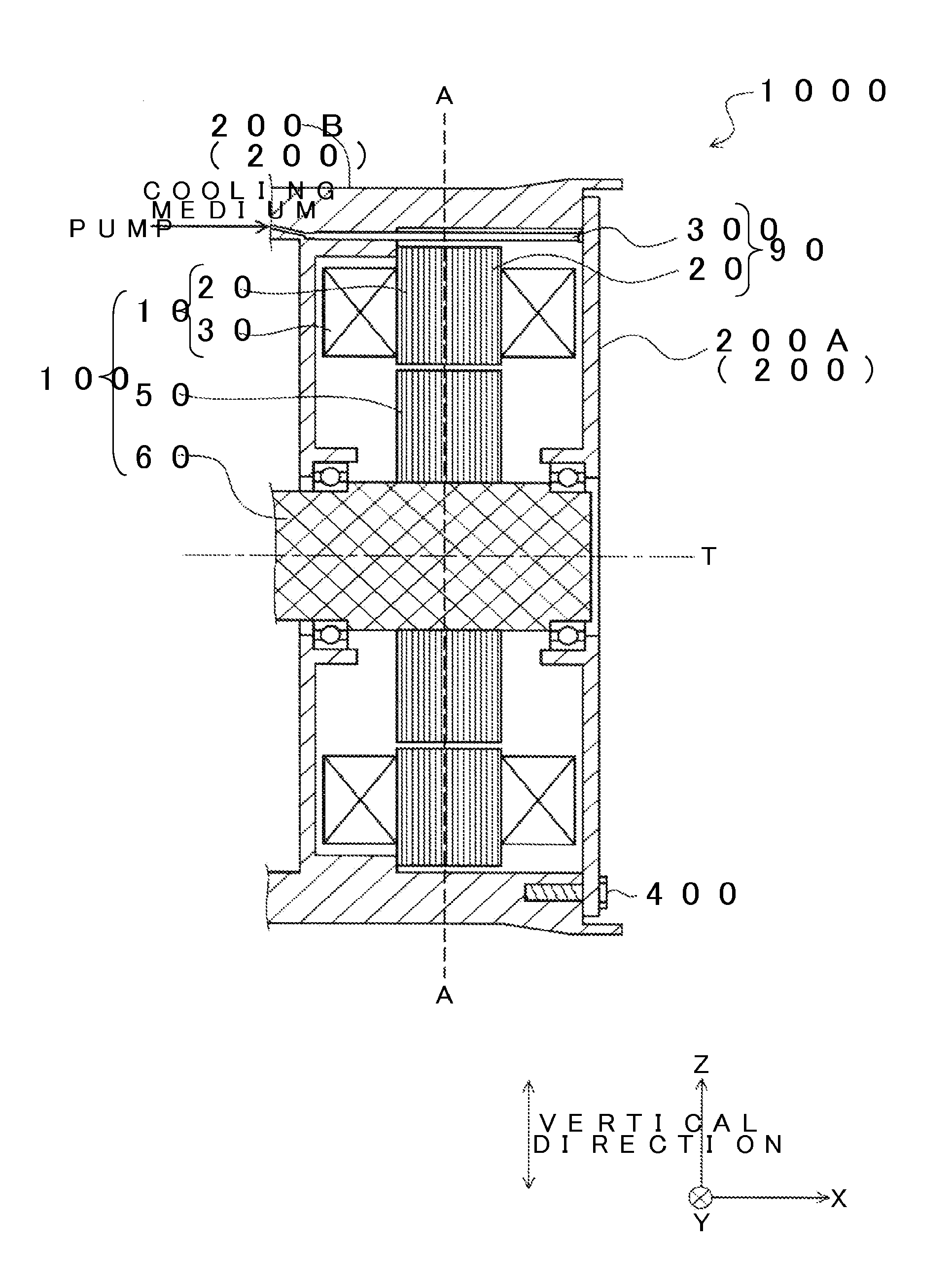
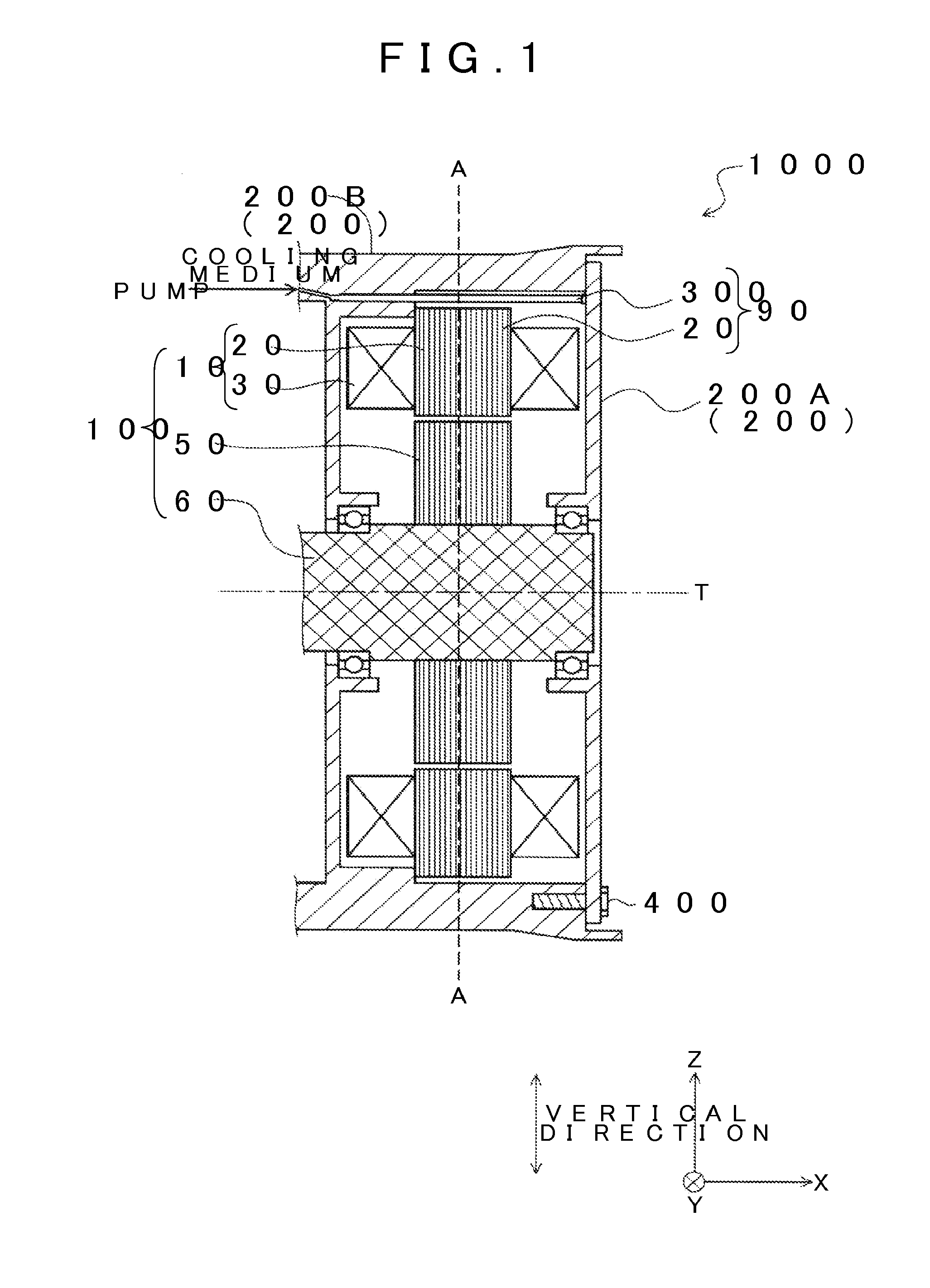
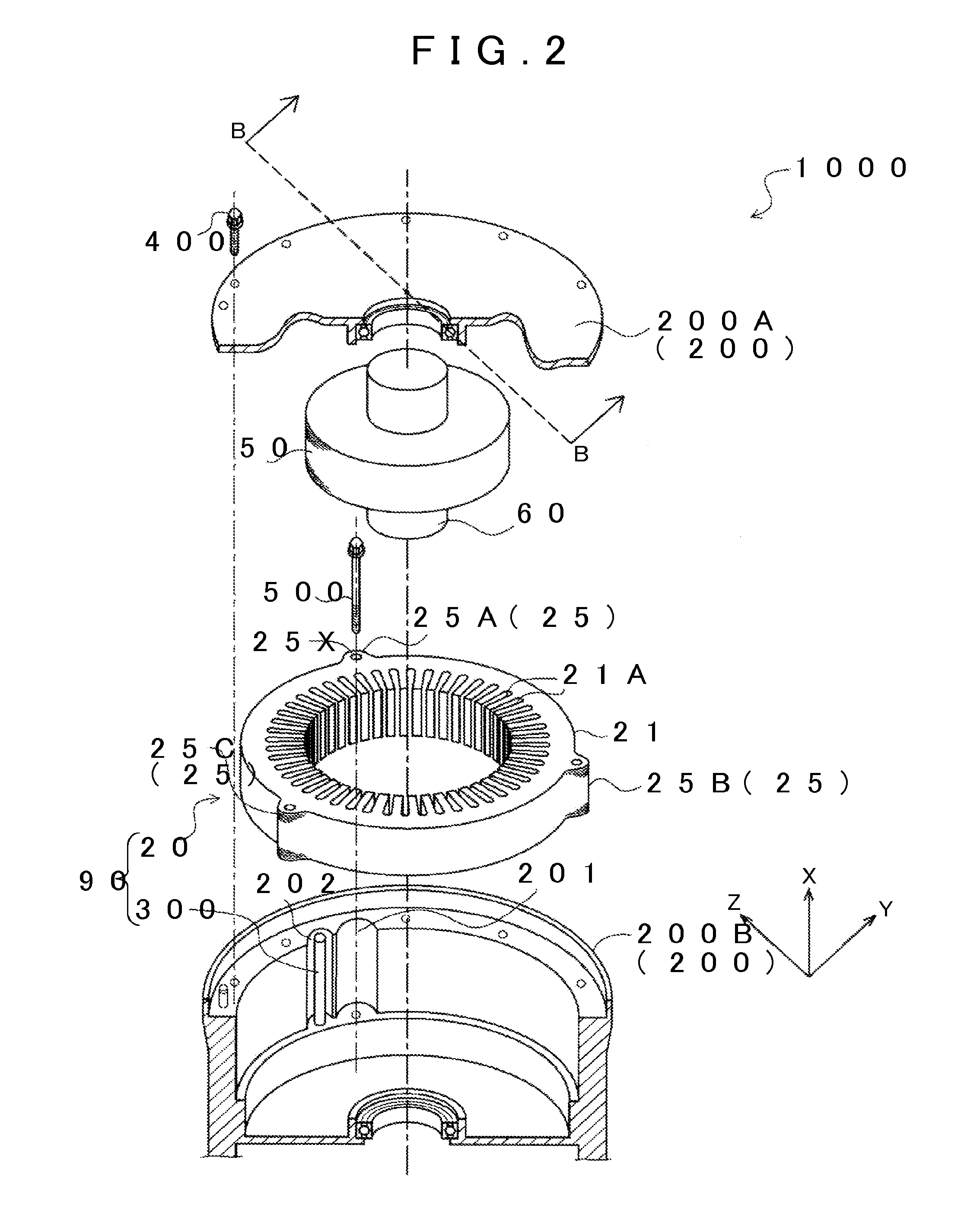
[0035]FIG. 1 is a view showing a cross section of a rotary electric machine unit 1000 serving as a first embodiment of the present invention. In FIG. 1, an up-down direction serves as a vertical direction, and a left-right direction serves as a horizontal direction. In addition, an x direction, a y direction, and a z direction are defined as illustrated in FIG. 1. The z direction is an upward direction along the vertical direction, and the x direction and the y direction are directions along the horizontal direction. The x direction is orthogonal to the y direction. The x direction is a rightward direction in FIG. 1, and the y direction is a direction extending along a direction heading into the paper in FIG. 1. FIG. 2 is an exploded perspective view showing the rotary electric machine unit 1000. FIG. 1 corresponds to a view of a cross section taken along a line B-B in FIG. 2 as viewed from the y direction. FIG. 3 i...
second embodiment
B. Second Embodiment
B1. Configuration of First Injection Hole 300A
[0060]FIG. 6 is a view showing the first injection hole 300A and the second injection hole 300B in the cooling medium flow passage 300 serving as a second embodiment. In the first embodiment, above, the first injection hole 300A and the second injection hole 300B are configured to have the same diameter. However, in the second embodiment, as shown in FIG. 6, the first injection hole 300A is configured to have a smaller diameter than the second injection hole 300B.
[0061]According to the cooling medium flow passage 300 of the present embodiment, as shown in FIG. 6, the first injection hole 300A has a smaller diameter than the second injection hole 300B. With this configuration, the cooling medium can be more strongly injected through the first injection hole 300A, compared to the second injection hole 300B. Accordingly, the cooling medium injected through the first injection hole 300A can easily pass over the first fixe...
modification examples
C. Modification Examples
[0062]It should be noted that structural elements described in the embodiments above other than the structural elements claimed in the independent claim are additional, and may be omitted as appropriate. Further, the present invention is not limited to the examples and embodiments above, and may be embodied in various modes without departing from the scope of the present invention. For example, the following modifications are possible.
PUM
 Abstract
Description
Claims
Application Information
 - R&D Engineer
- R&D Manager
- IP Professional
- Industry Leading Data Capabilities
- Powerful AI technology
- Patent DNA Extraction
Browse by: Latest US Patents, China's latest patents, Technical Efficacy Thesaurus, Application Domain, Technology Topic, Popular Technical Reports.
© 2024 PatSnap. All rights reserved.Legal|Privacy policy|Modern Slavery Act Transparency Statement|Sitemap|About US| Contact US: help@patsnap.com