Diffractive optical element and manufacturing method thereof

a technology manufacturing methods, applied in the field of diffractive optical elements, can solve the problems of uneven color and flare, low diffraction efficiency of light of any other wavelength, and difficulty in building an optical system having appropriate optical characteristics with diffractive optical elements alone, and achieve good optical characteristics

Active Publication Date: 2014-02-18
PANASONIC CORP
View PDF9 Cites 2 Cited by
  • Summary
  • Abstract
  • Description
  • Claims
  • Application Information

AI Technical Summary

Benefits of technology

[0034]According to the present invention, a body having a diffraction grating provided thereon and an optical adjustment layer are each composed of a resin-containing optical material, such that the difference between the solubility parameters of the two resins is no less than 0.8 [cal / cm3]1 / 2 and no more than 2.5 [cal / cm3]1 / 2. As a result, interaction between the resin of the body and the resin of the optical adjustment layer can be suppressed, thus providing a diffractive optical element having good optical characteristics in which deformation of the diffraction grating is suppressed and occurrence of unwanted diffracted light and stray light due to changes in the refractive index of the body is suppressed.

Problems solved by technology

However, since diffraction efficiency theoretically depends on light wavelength, there is a problem in that, if a diffractive optical element is designed so as to attain an optimum diffraction efficiency for light of a specific wavelength, its diffraction efficiency will be lower for light of any other wavelength.
For example, in the case where a diffractive optical element is employed in an optical system which utilizes white light, e.g., a lens for a camera, such wavelength dependence of diffraction efficiency will cause uneven color and flares due to light of unwanted orders, and thus it is difficult to construct an optical system having appropriate optical characteristics with diffractive optical elements alone.
However, when glass is used as the first optical material to become the body, micromachining becomes more difficult than in the case of a resin, and therefore it is not easy to obtain a narrow diffraction grating pitch for improving the diffraction performance.
Thus, it is difficult to enhance the optical performance while downsizing the optical element.
Moreover, since the molding temperature of glass is higher than that of resin, a mold for molding glass has a lower durability than that of a mold for molding resin, thus resulting in a producibility problem.
However, it is more difficult to realize various refractive index values than in the case of glass, so that the reduced refractive index difference between the first optical material and the second optical material is reduced, and thus the diffraction grating will have a large depth d, as is clear from eq.
As a result of this, although the body itself has an excellent processibility, the mold must be processed deep for forming the diffraction grating and the edges of the grooves must be shaped sharp, which makes the mold processing difficult.
Moreover, due to processing constraints of at least one of the body and the mold, the pitch of the diffraction grating need to be made larger as the diffraction grating becomes deeper.
Therefore, the number of the diffraction grating cannot be increased, and the design constraints of the diffractive optical element are increased.

Method used


Image

  • Diffractive optical element and manufacturing method thereof
  • Diffractive optical element and manufacturing method thereof
  • Diffractive optical element and manufacturing method thereof

Examples


first embodiment

(First Embodiment)

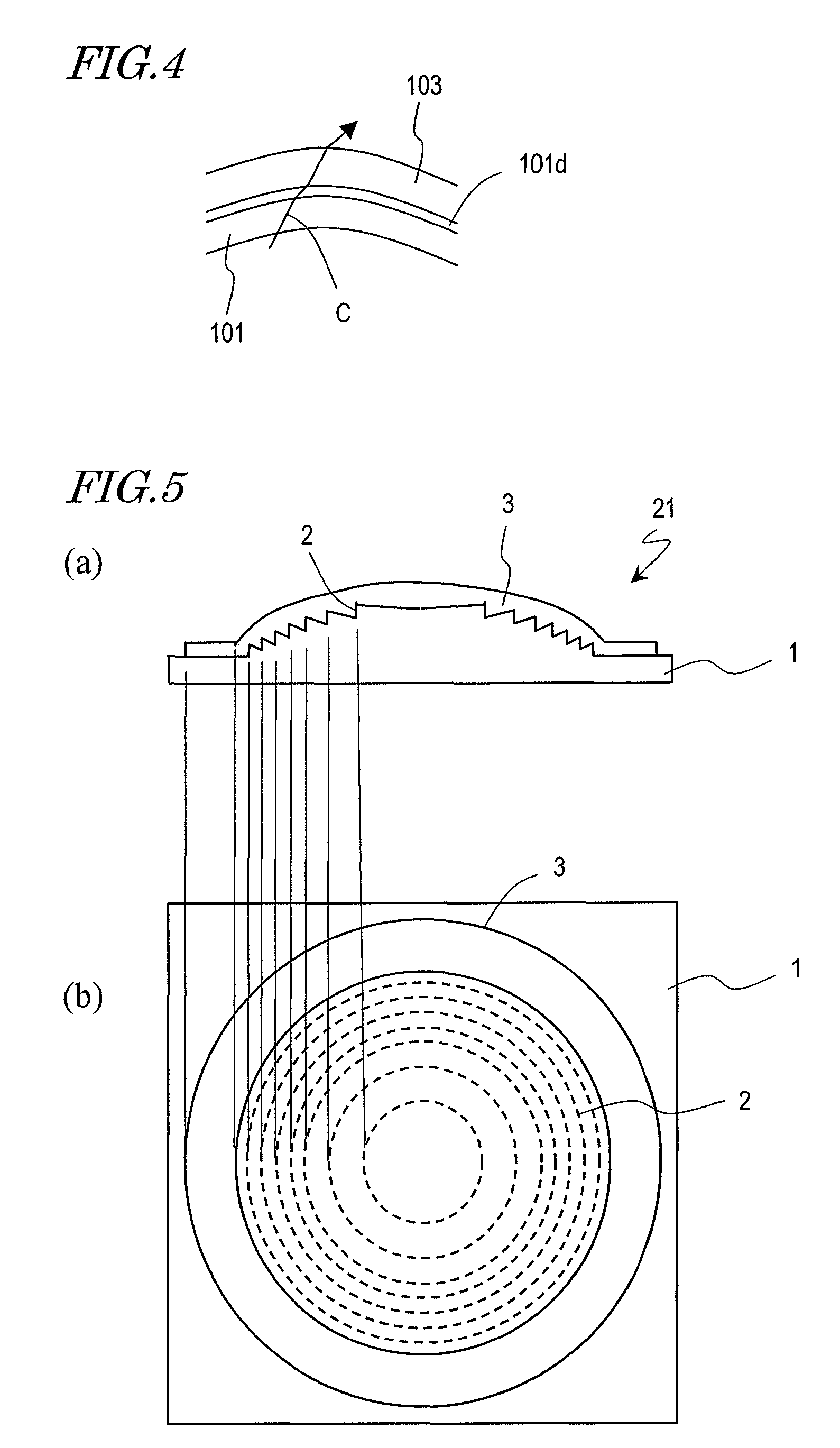
[0063]FIGS. 5(a) and (b) are a cross-sectional view and an upper plan view showing a first embodiment of the diffractive optical element according to the present invention. A diffractive optical element 21 shown in FIGS. 5(a) and (b) includes a body 1 and an optical adjustment layer 3.

[0064]The body 1 is composed of a first optical material containing a first resin, and has a diffraction grating 2 on its surface. In the present embodiment, the first optical material only contains the first resin. The cross-sectional shape, positioning, pitch, and depth of the diffraction grating 2 are to be determined based on the optical characteristics of the body 1 and the optical adjustment layer 3 and the optical characteristics which are required of the diffractive optical element 21. For example, in order to confer a lens action to the diffractive optical element 21, an annular diffraction grating having a sawtooth cross-sectional shape is provided in the form of concentric ...

second embodiment

(Second Embodiment)

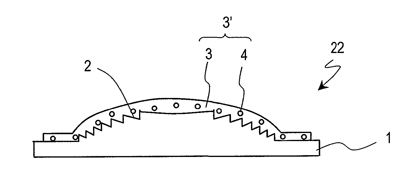
[0091]FIG. 6 is a cross-sectional view showing a second embodiment of the diffractive optical element according to the present invention. As shown in FIG. 6, a diffractive optical element 22 includes a body 1 and an optical adjustment layer 3′.

[0092]Similarly to the first embodiment, the body 1 is composed of a first optical material containing a first resin, and has a diffraction grating 2 on its surface. The diffraction grating 2 has a similar structure to that of the first embodiment.

[0093]A second optical material composing the optical adjustment layer 3′ contains a second resin 3 and inorganic particles 4. The second resin 3 and the inorganic particles 4 together compose a composite material such that the inorganic particles 4 are dispersed in a matrix of the second resin 3. The difference in solubility parameter between the first resin and the second resin 3 is equal to or greater than 0.8 [cal / cm3]1 / 2.

[0094]By using the composite material in which the inorg...

third embodiment

(Third Embodiment)

[0117]Hereinafter, an embodiment of a production method of the diffractive optical element according to the present invention will be described. In the present embodiment, with reference to FIGS. 7(a) to (f) and FIGS. 8(a) to (d), a method of producing the diffractive optical element 21 of the first embodiment will be described.

[0118]First, as shown in FIG. 7(a), a body 1 having a diffraction grating 2 formed on its surface is provided. For example, the body 1 having the diffraction grating 2 formed thereon can be produced by: a method of performing molding by supplying a first optical material in a softened or melted state into a mold in which a diffraction grating shape has been formed, such as injection molding or press forming; a method of injecting a monomer, oligomer, or the like as a raw material of the first optical material into a mold in which a diffraction grating shape has been formed, and polymerizing the raw material via heating and / or energy beam irr...


PUM

PropertyMeasurementUnit
particle sizeaaaaaaaaaa
viscosityaaaaaaaaaa

Abstract

A diffractive optical element according to the present invention includes: a body 1 being composed of a first optical material containing a first resin, and having a diffraction grating 2 on a surface thereof; and an optical adjustment layer 3 being composed of a second optical material containing a second resin, and provided on the body 1 so as to cover the diffraction grating 2. The first optical material has a refractive index which is smaller than a refractive index of the second optical material; the refractive index of the first optical material has a wavelength dispersion which is greater than a wavelength dispersion of the refractive index of the second optical material; and a difference in solubility parameter between the first resin and the second resin is no less than 0.8 [cal / cm3]1 / 2 and no more than 2.5 [cal / cm3]1 / 2.

Description

TECHNICAL FIELD[0001]The present invention relates to a diffractive optical element, and relates to a diffractive optical element which is composed of two or more members respectively containing different resins, and a production method thereof.BACKGROUND ART[0002]A diffractive optical element is structured so that a diffraction grating for diffracting light is provided on a body which is composed of an optical material such as a glass or a resin. Diffractive optical elements are used in the optical systems of various optical devices, including imaging devices and optical recording apparatuses. For example, lenses which are designed to gather diffracted light of a specific order to one point, spatial low-pass filters, polarizing holograms, and the like are known.[0003]A diffractive optical element has an advantage in that it allows for a compact optical system. Moreover, conversely to refraction, a greater diffraction occurs for light of longer wavelengths. Therefore, by combining a...

Claims


Application Information

Patent Timeline
Patent Type & Authority Patents(United States)
IPC IPC(8): B32B5/16B32B27/30B32B7/02G02B1/04G02B5/18
CPCG02B5/1866G02B5/1814G02B5/1857B29D11/0073B29D11/00769Y10T428/25Y10T428/256Y10T428/257Y10T428/258Y10T428/24942Y10T428/259
Inventor MURATA, AKIKOOKADA, YUKA
Owner PANASONIC CORP
Why Eureka
Try Eureka