Electrical contact coupling for a track-borne vehicle, particularly a railway vehicle

a technology for electric contact coupling and track-borne vehicles, which is applied in the direction of coupling contact members, coupling device connections, transportation and packaging, etc., can solve the problems of reducing surface resistance, lateral sealing gaps between the protective flap and the coupling housing, and reducing maintenance costs. , to achieve the effect of reducing maintenance expenditures and ensuring the seal

Inactive Publication Date: 2014-02-18
VOITH PATENT GMBH
View PDF12 Cites 0 Cited by
  • Summary
  • Abstract
  • Description
  • Claims
  • Application Information

AI Technical Summary

Benefits of technology

[0010]The invention is based on the task of specifying an electrical contact coupling having a protective flap able to be pivoted relative the coupling housing by means of a simple mechanism which nevertheless achieves a greater seal against dust and moisture so as to reduce maintenance expenditures and also enable usage of coupling elements for optical data transmission.
[0015]The advantages which can be achieved with the inventive solution are obvious. By the protective flap being pivotable relative to the coupling housing about a fixed axis of rotation dispenses with the need for a complex mechanism to pivot the protective flap. Instead, the protective flap can be connected to the coupling housing by means of a single-joint hinge. Because no complicated hinging structure, for instance a four-joint system, etc., needs to be used to pivot the protective flap, the electrical contact coupling can be realized as a more simple structure on the whole and thus be of more economical and compact design.
[0018]In order to be able to also effectively seal the lateral sealing gaps between the upper and lower sealing area in the closed state of the electrical contact coupling, the invention provides for the seal to further comprise a lateral sealing area to connect the upper sealing area with the lower sealing area. The contact area of the protective flap exhibits an associated section corresponding to the lateral sealing area which contacts said lateral sealing area when the protective flap is in the first position. To prevent the section of the contact area allocated to the lateral sealing area from rubbing against the lateral sealing area when the electrical contact coupling is being opened; i.e. when the protective flap transits from its first (closed) position into its second (open) position, it is inventively provided for the section of the contact area associated with the lateral sealing area to be configured as a three-dimensional sealing face which continuously adjoins the sealing face aligned substantially perpendicular to the housing end face to the sealing face aligned substantially parallel to the housing end face.

Problems solved by technology

However, using single-joint hinges to pivot the protective flap does have the disadvantage that when the protective flap is in the closed position, the flap contour does not seat completely solidly on the sealing face of the coupling housing, respectively the sealing face of the coupling housing's front frame, and thus neither is an effective sealing usually possible, the main problem thereby being the lateral sealing gaps between the protective flap and the coupling housing.
The lateral cracks thus present when the protective flap is in the closed position can allow the infiltration of dust, particularly metallic dust, and moisture, which can lead to reduced surface resistance.
Abrasive dirt particles can also infiltrate, causing increased wear on the electrical contacts.
If additional seals are used to seal the lateral sealing gaps between the protective flap and the coupling housing in the closed position of the protective flap, friction acting on the lateral sealing elements cannot be avoided when the protective flap is opened and closed, which leads to increased wear on the lateral sealing elements.

Method used


Image

  • Electrical contact coupling for a track-borne vehicle, particularly a railway vehicle
  • Electrical contact coupling for a track-borne vehicle, particularly a railway vehicle
  • Electrical contact coupling for a track-borne vehicle, particularly a railway vehicle

Examples


Embodiment Construction

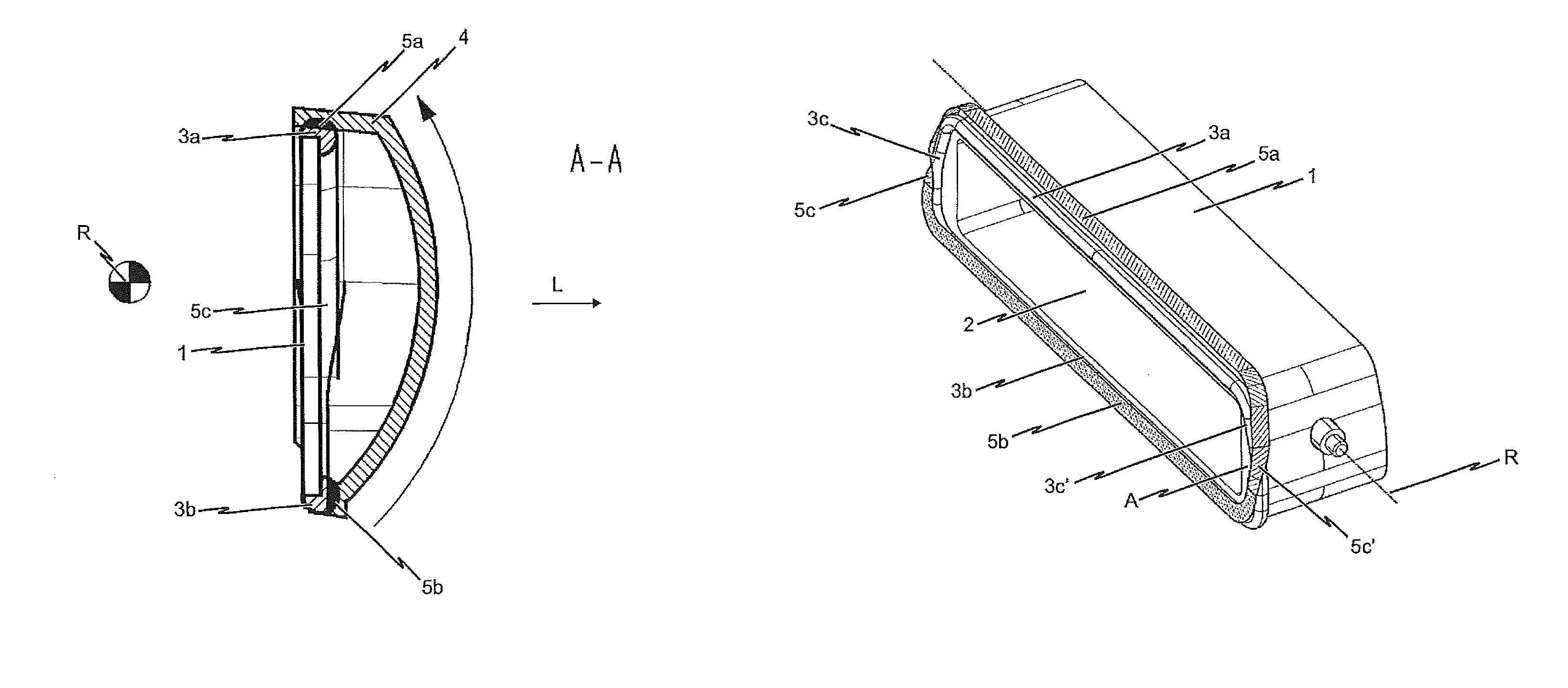
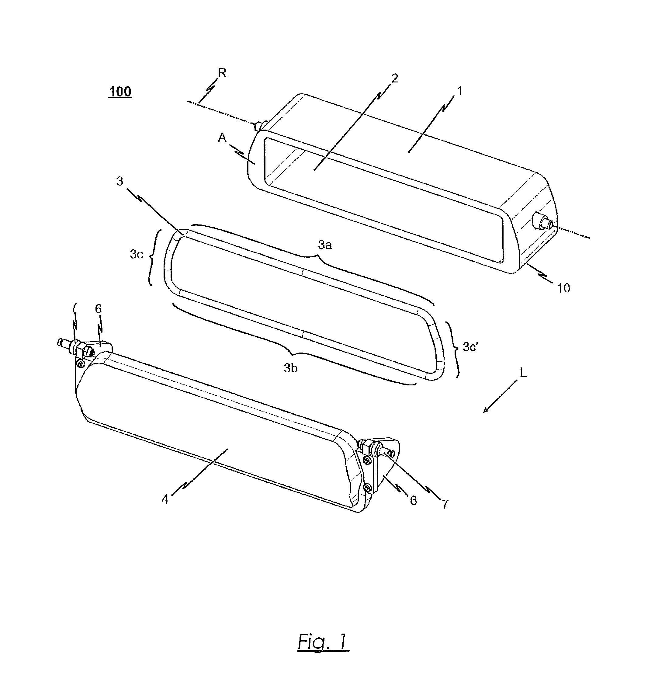
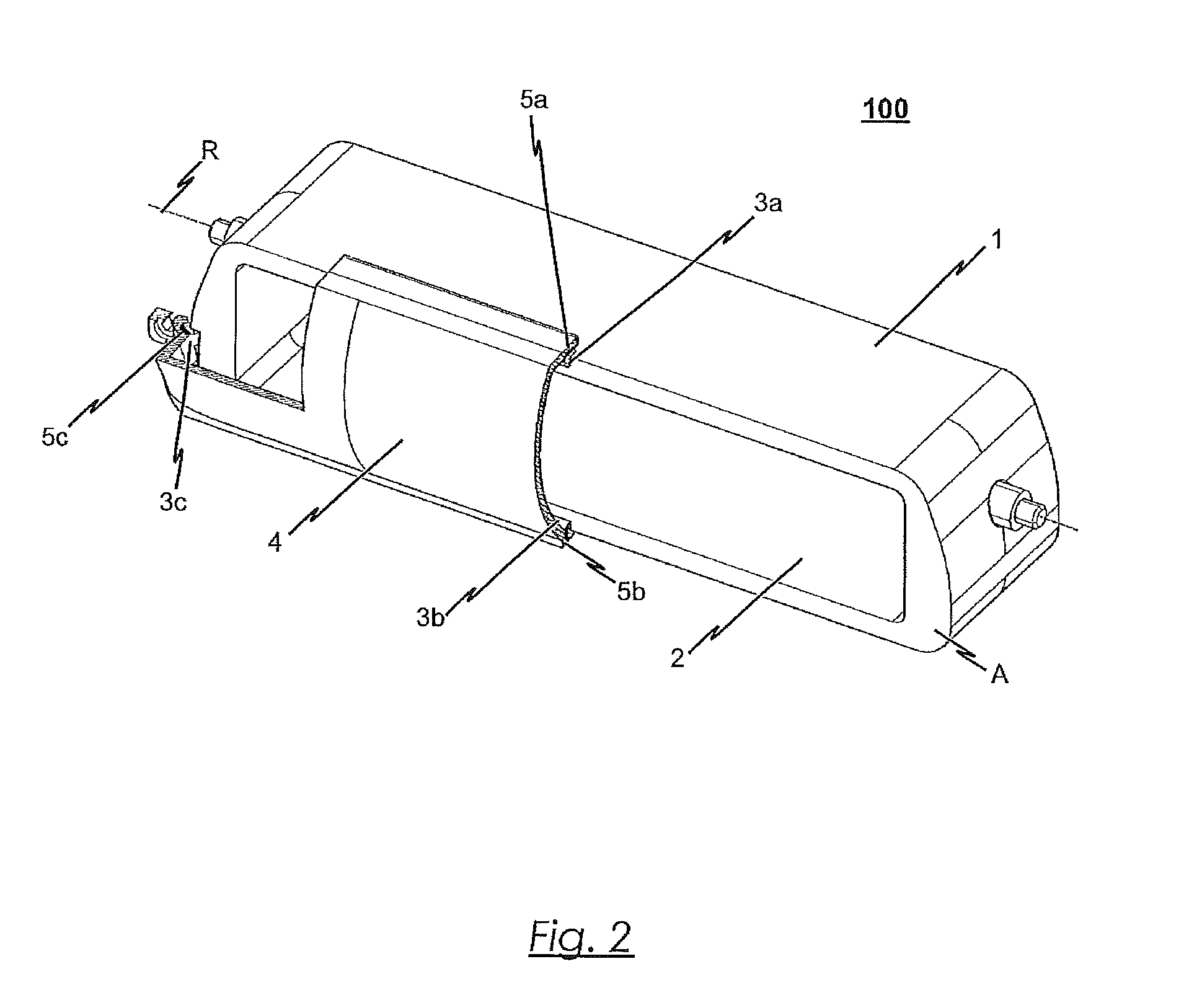
[0037]The electrical contact coupling 100 depicted as an embodiment in the drawings is designed to be fixable to a track-borne vehicle, a railway vehicle in particular, such that the housing end face A of the electrical contact coupling 100 faces the vehicle's coupling direction L and lies in coupling plane M or can be brought into coupling plane M. The electrical contact coupling 100 thereby serves, in conjunction with an electrical contact coupling 100′ configured complementary thereto (see FIG. 6), to establish a connection between electrical lines and / or signal lines between two neighboring vehicles, in particular railway vehicles.

[0038]As can be seen from the exploded view of FIG. 1, the electrical contact coupling 100 according to the depicted embodiment exhibits a trapezoidal coupling housing 1, on the bottom or base 10 (FIG. 6) of which guide bushings (not shown) can be arranged for displaceably mounting the coupling housing 1 in coupling direction L to a vehicle, in particu...


PUM


Abstract

An electrical contact coupling for a track-borne vehicle has a coupling housing and a protective flap articulated to the coupling housing. In order to ensure a reliable sealing of the coupling housing in the closed state of the electrical contact coupling, a seal is utilized which exhibits an upper sealing area running parallel to the axis of rotation and a lower sealing area running parallel to the axis of rotation. The upper sealing area associates with a sealing face aligned perpendicular to the housing end face and the lower sealing area associates with a sealing face aligned substantially parallel to the housing end face.

Description

BACKGROUND OF THE INVENTION[0001]1. Field of the Invention[0002]The invention relates to an electrical contact coupling for a track-borne vehicle, particularly a railway vehicle.[0003]Electrical contact couplings are usually employed in rail vehicle technology to transmit control signals and power between two neighboring car bodies of a multi-member vehicle. The arrangement, control and size of the electrical contact couplings employed depend on the installation space available in the vehicle and on the number of signals to be transmitted as well as the requirements of the rail car manufacturer and / or the railway operator.[0004]2. The Prior Art[0005]Electrical contact couplings are usually configured such that two electrical contact couplings can be coupled and uncoupled automatically. To that end, the electrical contact couplings arranged on the vehicles or car bodies to be coupled are precisely joined together by means of centering devices and then the sealing surfaces configured ...

Claims


Application Information

Patent Timeline
Patent Type & Authority Patents(United States)
IPC IPC(8): B61G5/10
CPCH01R13/5219H01R13/5213B61G5/10B61G5/06
Inventor LYDA, MARTINWENGE, BRUNHILDEHEMPEL, MARIO
Owner VOITH PATENT GMBH
Why Eureka
Try Eureka