
Synchronization of illumination source and sensor for improved visualization of subcutaneous structures

a technology of illumination source and sensor, which is applied in the field of medical devices and procedures, can solve the problems of significantly and achieve the effect of reducing the temperature of the lighting package and enhancing power levels

Active Publication Date: 2014-02-11
US SEC THE AIR FORCE THE
View PDF18 Cites 110 Cited by
  • Summary
  • Abstract
  • Description
  • Claims
  • Application Information

AI Technical Summary

Benefits of technology

This approach enables enhanced visualization of subcutaneous structures with improved image quality and the ability to use higher power NIR illumination sources without excessive heat, facilitating medical procedures like vascular access and foreign structure detection under normal lighting conditions.

Problems solved by technology

Further, this technique significantly reduces the temperature of the lighting package when it is a necessary or optimal part of an illumination source that must be in contact with patients.

Method used


Image

  • Synchronization of illumination source and sensor for improved visualization of subcutaneous structures
  • Synchronization of illumination source and sensor for improved visualization of subcutaneous structures
  • Synchronization of illumination source and sensor for improved visualization of subcutaneous structures

Examples


Embodiment Construction

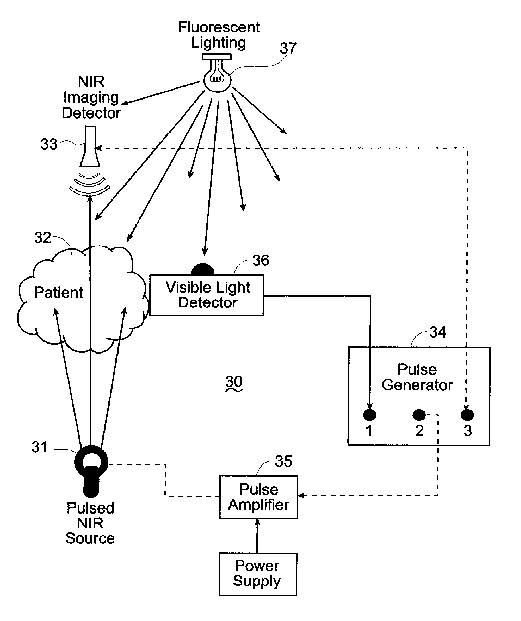
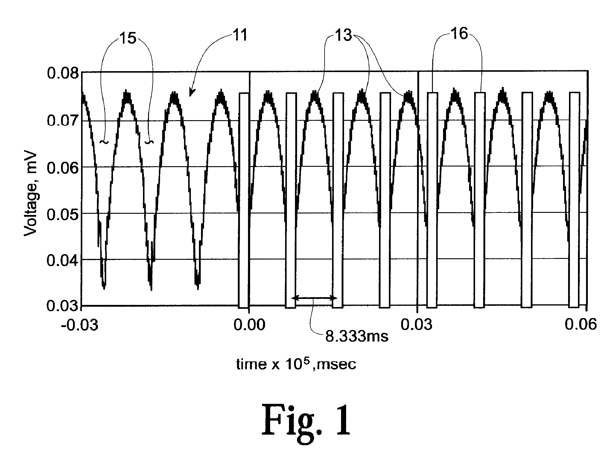
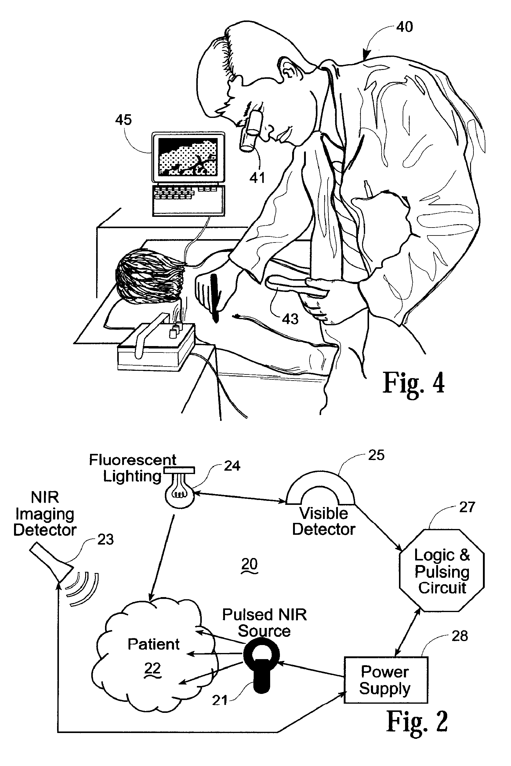
[0035]Referring now to the drawings, FIG. 1 shows a plot 11 of voltage versus time defining the optical power output from a typical commercially available fluorescent light bulb. Background lighting in a medical treatment environment may have as its source incandescent, LED, or other pulsed illumination, as well as fluorescent illumination. The invention is, however, described herein in consideration of fluorescent background lighting as representative of the lighting under which the invention may be operative, with the understanding that the invention can be practiced, within the scope of these teachings and the appended claims, under conditions of other pulsed lighting.

[0036]In accordance with a feature of the invention, and considering fluorescent background lighting as an example, it is recognized that fluorescent illumination is produced as a full wave rectified sine wave with a frequency of 120 Hz. If the artificial lighting is applied in conjunction with the practice of the i...


PUM

PropertyMeasurementUnit
wavelength rangeaaaaaaaaaa
frequencyaaaaaaaaaa

Abstract

System and method are described for synchronizing a pulsed source of the near infrared illumination used in visualizing subcutaneous structures with the background illumination normally extant in medical treatment settings that allow both enhanced image acquisition and use of higher power pulsed infrared illumination sources.

Description

CROSS REFERENCE TO RELATED APPLICATION[0001]This application claims priority of the filing date of Provisional Application Ser. No. 60 / 786,880 filed Mar. 28, 2006.STATEMENT OF GOVERNMENT INTEREST[0002]The invention described herein was made under a Cooperative Research and Development Agreement number 02-161-ML-01 with the Department of The Air Force. The Government of the United States has certain rights in the invention.FIELD OF THE INVENTION[0003]The invention described herein relates generally to medical devices and procedures for access to human or animal vasculature, and more particularly to system and method for enhanced visualization of subcutaneous structures under ambient lighting from fluorescent, incandescent, light emitting diode (LED) or other illumination source.BACKGROUND OF THE INVENTION[0004]The use of near infrared (NIR) radiation for diagnostic procedures in the human body has traditionally been limited by the inability to transmit NIR radiation into and through ...

Claims


Application Information

Patent Timeline
Patent Type & Authority Patents(United States)
IPC IPC(8): A61B6/00G02F1/01
CPCA61B5/0059A61B5/489A61B5/742A61B5/0086
Inventor CRANE, ROBERT L.BUCHIN, MICHAEL P.
Owner US SEC THE AIR FORCE THE
Learn More