
Multiple force-measuring device, force-measuring module, and method for monitoring a condition of the multiple force-measuring device

a technology of multiple force measurement and force measurement module, which is applied in the direction of measuring device, weighing apparatus details, instruments, etc., can solve the problems of increased susceptibility to interference, increased probability of errors in installation process as well as during operation and maintenance, and increased cos

Active Publication Date: 2014-02-11
METTLER TOLEDO GMBH
View PDF37 Cites 7 Cited by
  • Summary
  • Abstract
  • Description
  • Claims
  • Application Information

AI Technical Summary

Benefits of technology

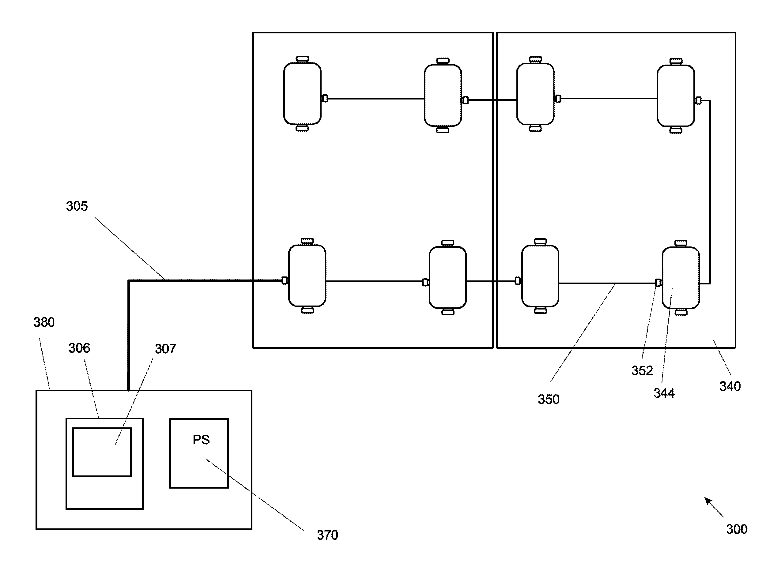
The patent describes a multiple force-measuring device that has multiple force-measuring modules with their own power supply units connected to each other through a module-connection cable. This design reduces the overall cable length, making it cost-effective and easy to maintain. Each force-measuring module has its own plug connector for easy setting up, testing, and servicing. The technical effect of this design is a simplified, cost-effective, and efficient way to measure forces.

Problems solved by technology

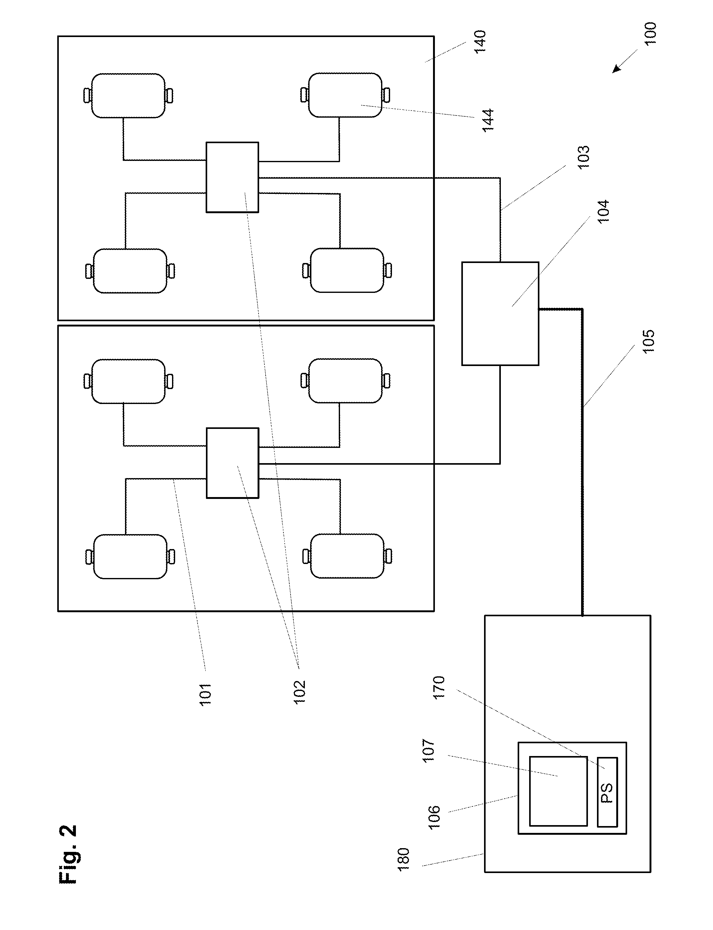
However, the distribution devices are expensive and susceptible to interference.
The probability of errors in the installation process as well as during operation and maintenance increases with the rising number of components.
Nevertheless, in most cases this arrangement involves longer distribution leads and a larger overall length of the distribution leads, thus an increased susceptibility to interference and higher costs.
However, this solution has the disadvantage that the charge level of the batteries has to be checked at regular intervals, and that insufficiently charged batteries have to be recharged or exchanged.
This limitation of the current is particularly important in hazardous environments where an explosion danger exists and where special regulatory requirements have to be met in regard to the maximum current consumption of the force-measuring modules and / or the force-measuring device.

Method used


Image

  • Multiple force-measuring device, force-measuring module, and method for monitoring a condition of the multiple force-measuring device
  • Multiple force-measuring device, force-measuring module, and method for monitoring a condition of the multiple force-measuring device
  • Multiple force-measuring device, force-measuring module, and method for monitoring a condition of the multiple force-measuring device

Examples


Embodiment Construction

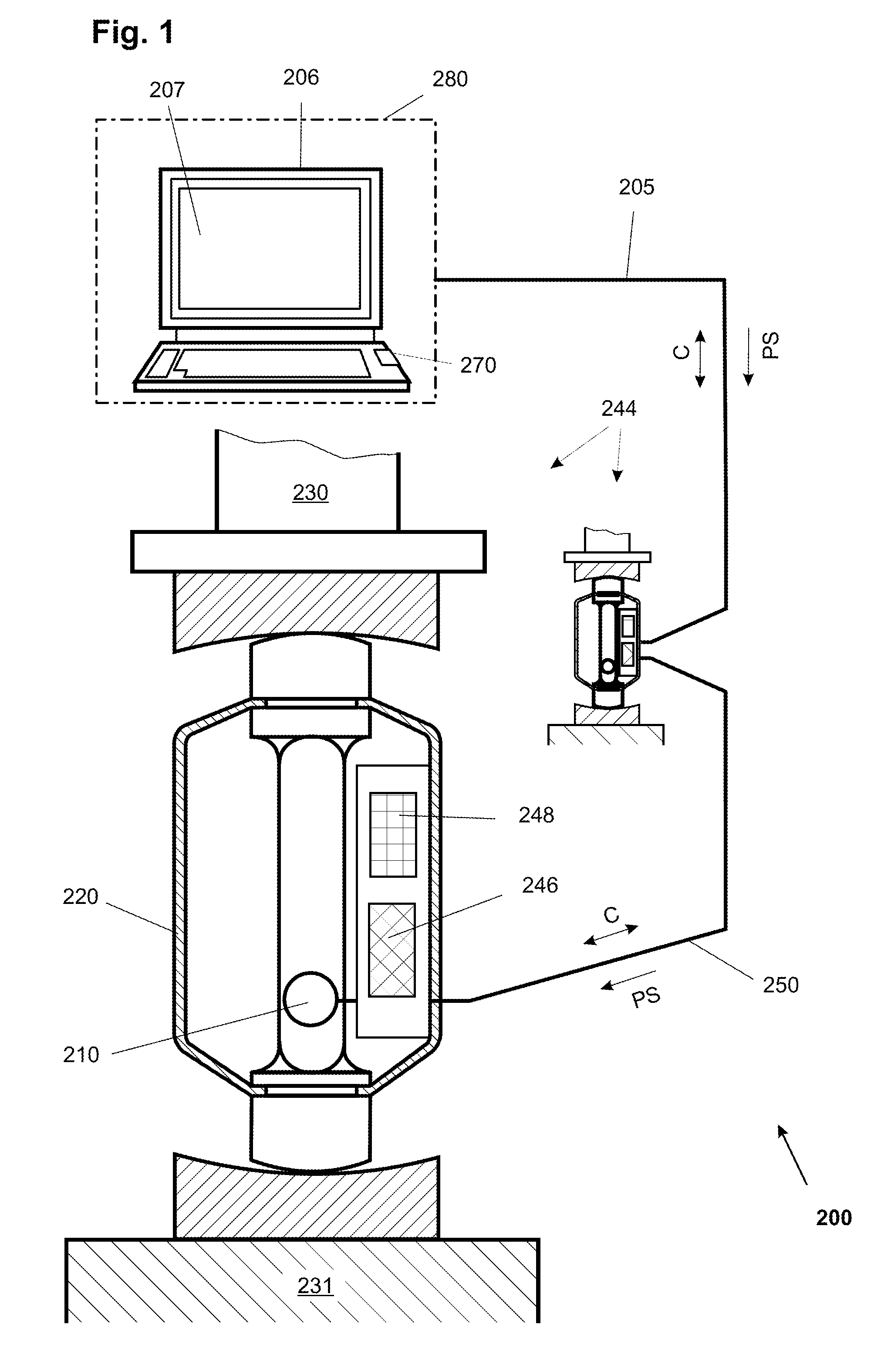
[0044]FIG. 1 shows a multiple force-measuring device 200 in the form of a tank-load weighing device. For the weighing of a container, a plurality of force-measuring modules 244 are arranged between the feet of the container 230 and the foundation 231, so that each foot of the container 230 rests on a force-measuring module 244. In order to determine the weight of the container and / or of its contents, the measurement values determined by the force-measuring modules 244 need to be added, as each measurement value represents a part of the mass. To perform the addition, the measurement values of the individual force-measuring modules 244 are transmitted to a terminal 206, where they are processed and presented on the display 207. The terminal 206 is arranged in a remotely located controller device 280.

[0045]The force-measuring module 244 includes a force-measuring cell 210 which is enclosed in a housing 220. Typically, the housing 220 is welded to the force-measuring cell 210 and tightl...


PUM


Abstract

A multiple force-measuring device, especially a multiple weighing device has at least two force-measuring modules. Each force-measuring module includes a force-measuring cell and a power delivery means. The power delivery means of at least one of the force-measuring modules in this arrangement is connected, directly or through a junction element, to a control cable that is connected to a power supply unit. The force-measuring modules are connected directly to each other through a module-connection cable that transfers electrical power therebetween.

Description

CROSS-REFERENCE TO RELATED APPLICATIONS[0001]This application is a continuation under 35 USC §120 of PCT / EP2008 / 053623, filed 27 Mar. 2008, which is in turn entitled to benefit of a right of priority under 35 USC §119 from U.S. provisional application 60 / 942468, filed 7 Jun. 2007. The content of each of the applications is incorporated by reference as if fully recited herein.TECHNICAL FIELD[0002]The disclosed embodiments relate to a multiple force-measuring device, in particular a multiple weight-measuring device, and to a force-measuring module, as well as a method of operating the force-measuring device.BACKGROUND OF THE ART[0003]Under the definition used herein, a multiple force-measuring device includes at least two force-measuring modules and an indicator device. The force-measuring module, in turn, includes an electromechanical force-measuring cell serving to determine a force, which functions as a measurement converter in that it converts the input quantity, which is a mechan...

Claims


Application Information

Patent Timeline
Patent Type & Authority Patents(United States)
IPC IPC(8): G01G19/00
CPCG01G23/3707G01G23/01
Inventor BUCHER, CYRILLSKIDMORE, AARONBLISS, DOUGLASUSTER, MARKUS
Owner METTLER TOLEDO GMBH
Learn More