
Apparatus and method for OLT and ONU for wavelength agnostic wavelength-division multiplexed passive optical networks

a technology of wavelength-agnostic wavelengthdivision and optical network, applied in multiplex communication, semiconductor amplifier structure, semiconductor lasers, etc., can solve the problems of reducing the extinction ratio (er) of the input optical sufficiently, the power penalty of upstream transmission is reduced, and the transmission quality of upstream transmission is getting worse. , to achieve the effect of reducing the thickness of a level ‘1, reducing the extinction ratio of the input optical signal, and reducing the power penalty o

Active Publication Date: 2014-02-04
ELECTRONICS & TELECOMM RES INST
View PDF18 Cites 2 Cited by
  • Summary
  • Abstract
  • Description
  • Claims
  • Application Information

AI Technical Summary

Benefits of technology

The present invention provides improvements in the transmission quality and reliability of optical signals in a Wavelength-Division-Multiplexed-Passive Optical Network (WDM-PON) by addressing the problem of limited compression performance of amplifiers and reducing the extinction ratio of optical signals. The invention also addresses the issue of wavelength stability and improves system stability by using a multi-wavelength light source and a wavelength-agnostic optical transmitter for the Optical Line Terminal (OLT). Additionally, the invention achieves wavelength independence of the OLT by injecting a seed light from a multi-wavelength light source and using a wavelength-agnostic optical transmitter for the OLT. This allows the OLT to process different wavelengths using a single optical transmission part regardless of the number of used WDM-based optical wavelengths.

Problems solved by technology

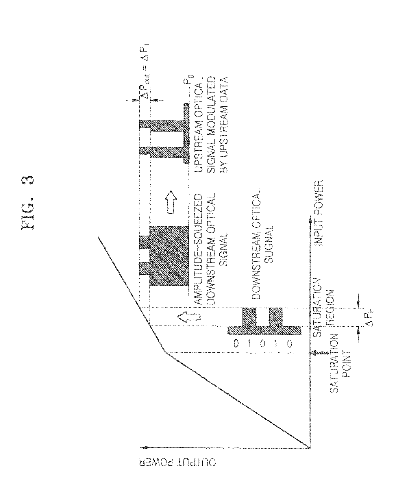
However, in actuality, the compressing ability of the RSOA in the gain saturation region is limited, and therefore, there is a limit in reducing an extinction ratio (ER) of the input optical sufficiently.
As the level ‘1’ is thicker, upstream transmission quality is getting worse.
If the level ‘1’ is thicker than a certain thickness, the upstream transmission quality is getting worse rapidly.
At this time, due to the low extinction ratio of the downstream optical signal, power penalty may occur in downstream transmission.
Especially, when the optical wavelengths of apparatuses configuring a downstream link are even slightly misarranged, there appears sensitivity by which the extinction ratio of an optical signal input into a receiver is getting less than the extinction of an optical signal output from a transmitter, and the transmitting quality is getting worse rapidly.
The manufacturing, installation and management of light sources according to wavelengths give a great load to all of users and providers, and thus increase system costs.
That is, in the WDM-PON according to the conventional downstream optical signal reusing method, an inventory problem occurs that different types of optical transmitters should be provided for the operation, management, replacement, etc. of systems.

Method used


Image

  • Apparatus and method for OLT and ONU for wavelength agnostic wavelength-division multiplexed passive optical networks
  • Apparatus and method for OLT and ONU for wavelength agnostic wavelength-division multiplexed passive optical networks
  • Apparatus and method for OLT and ONU for wavelength agnostic wavelength-division multiplexed passive optical networks

Examples


first embodiment

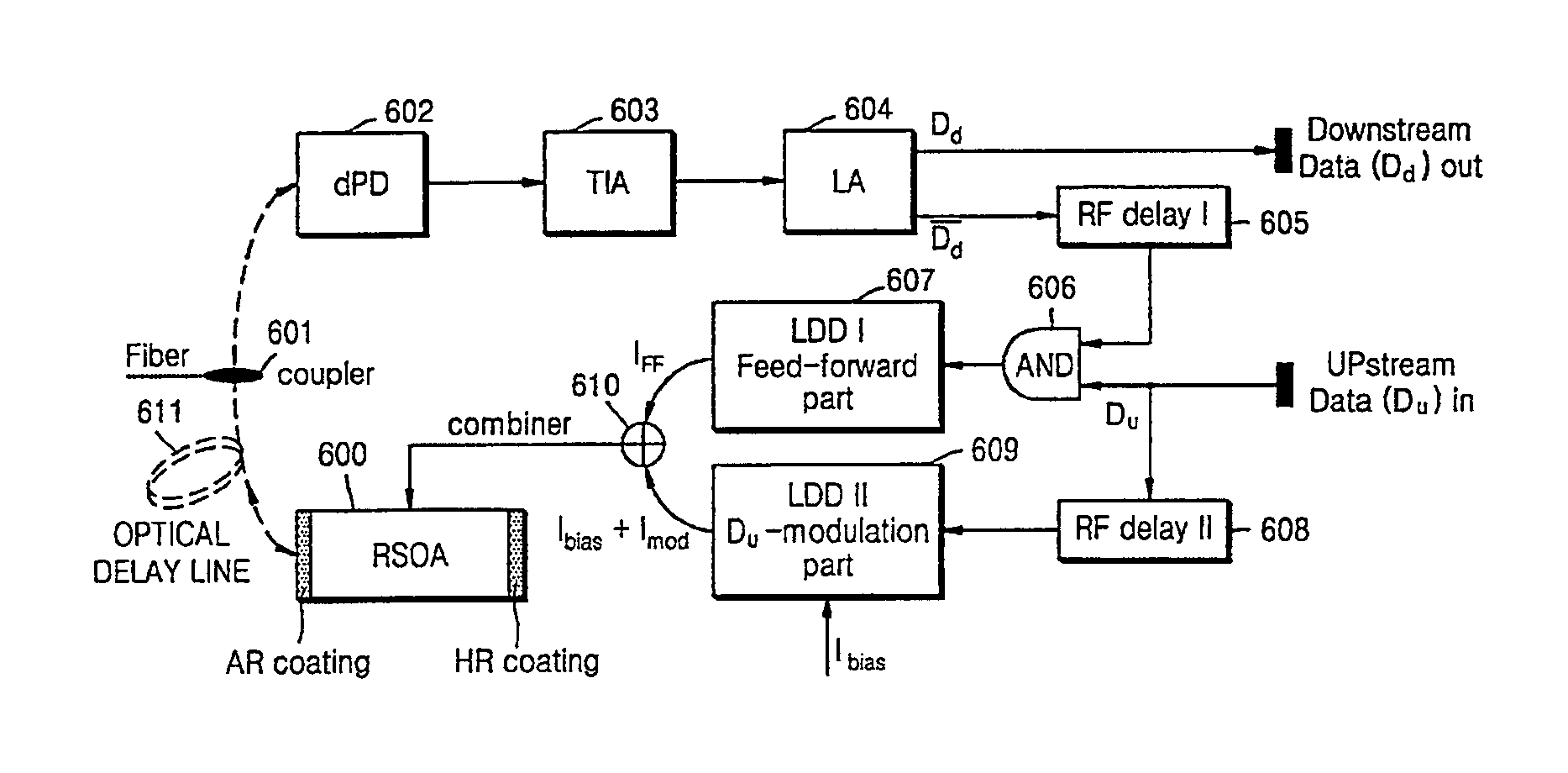
[0045]FIG. 6 illustrates a driving circuit for injecting feed-forward current into an RSOA including a single active region, according to the present invention;

second embodiment

[0046]FIG. 7 illustrates a driving circuit for injecting feed-forward current into an RSOA, including a single active region, according to the present invention;

third embodiment

[0047]FIG. 8 illustrates a driving circuit for injecting feed-forward current into a RSOA including a single active region, according to the present invention;

[0048]FIG. 9 illustrates a driving circuit for injecting feed-forward current into a RSOA, including a single active region, according to a first embodiment of the present invention;

[0049]FIG. 10 illustrates a driving circuit for injecting feed-forward current into a RSOA, including two active regions, according to a second embodiment of the present invention;

[0050]FIG. 11 illustrates a driving circuit for injecting feed-forward current into a RSOA including a single active region, according to a third embodiment of the present invention;

[0051]FIG. 12 illustrates the structure of a RSOA including three active regions to improve the flatness of an input optical signal, according to an embodiment of the present invention;

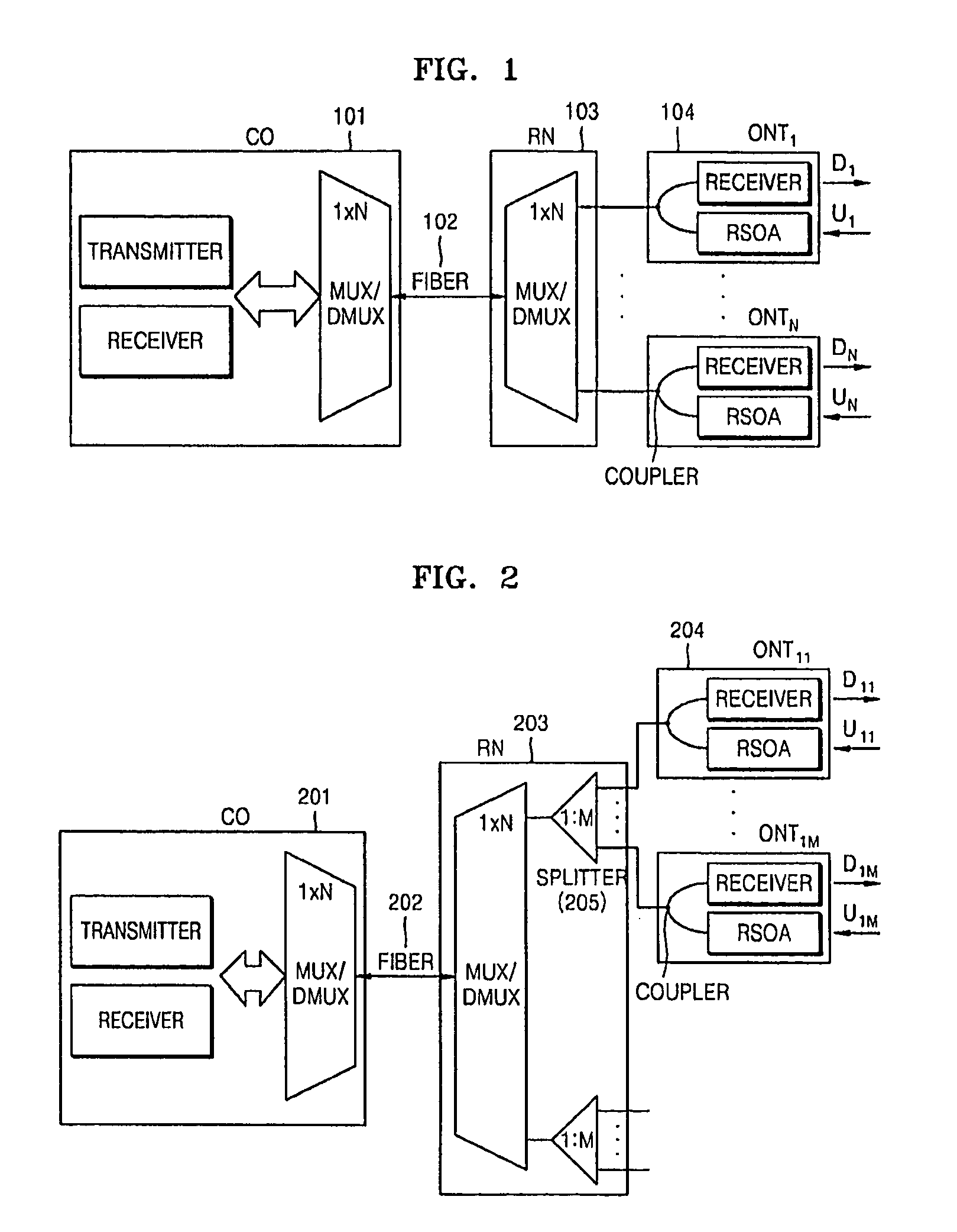
[0052]FIG. 13 is a configuration diagram of a WDM-PON according to a conventional downstream optical signal r...


PUM


Abstract

In a Wavelength-Division-Multiplexed Passive Optical Network (WDM-PON) utilizing a conventional downstream optical signal reusing method, there is an inventory problem that different optical transmitter types need to be provided for the operation, management, replacement, etc. of a system. A WDM-PON system according to the present invention, includes: a seed light (SL) unit generating a seed light whose wavelength intervals and center wavelengths are adjusted using at least one seed light source; an optical line terminal (OLT) receiving the wavelength-multiplexed seed light from the seed light unit, transmitting a downstream optical signal to a subscriber of the WDM-PON, and receiving a upstream optical signal from the subscriber; and an optical network unit (ONU) receiving the downstream optical signal from the OLT, flattening and modulating the downstream optical signal with upstream data so that the downstream optical signal is reused for carrying upstream data. It is possible to improve the quality and reliability of downstream transmission by sufficiently increasing an extinction ratio, and improve the quality and reliability of upstream transmission by sufficiently flattening an input downstream optical signal in a semiconductor optical amplifier.

Description

[0001]This is a non-provisional application claiming the benefit of International application number PCT / KR2007 / 003308 filed Jul. 6, 2007.TECHNICAL FIELD[0002]The present invention relates to a method for flattening a modulated optical signal in a Reflective Semiconductor Optical Amplifier (RSOA) or Semiconductor Optical Amplifier (SOA) to reuse the resultant optical signal as a upstream optical signal, and more particularly, to a driving apparatus for improving the flatness of an input optical signal and reusing the optical signal by injecting a signal whose polarity is opposite to that of the optical signal to a RSOA, and a SOA structure therefor.[0003]The present invention relates to a downstream optical transmission apparatus and method using a wavelength-agnostic light source in a Wavelength-Division-Multiplexed Passive Optical Network (WDM-PON), and an optical line terminal (OLT) using the downstream optical transmission apparatus, and more particularly, to a downstream optica...

Claims


Application Information

Patent Timeline
Patent Type & Authority Patents(United States)
IPC IPC(8): H04B10/40H04J14/02H04B10/07H04B10/2507H04B10/2587H04B10/27H04B10/272H04B10/50H04B10/54H04B10/60H04J14/00
CPCH01S5/06812H01S5/0427H01S5/5018H01S5/06253H04J14/025H04J2014/0253H01S5/50H04J14/0227H04J14/0282H04J14/02H04J14/0252H04J14/0246H04J14/0247H04J14/0307
Inventor KIM, BYOUNG-WHIPARK, MANYONGLEE, WOO-RAMKIM, BONG-TAECHO, SEUNG-HYUNLEE, JIE-HYUNJEONG, GEONKIM, CHULYOUNGKIM, DAE-UNGKANG, BYUNG-YONG
Owner ELECTRONICS & TELECOMM RES INST
Learn More