Terminal circuit and bi-directional coupler using the terminal circuit
a terminal circuit and bi-directional coupler technology, applied in the direction of coupling devices, electrical devices, waveguides, etc., can solve the problems of increasing return loss, reducing the isolation of the coupler, and inaccurate termination values of the terminal resistor
- Summary
- Abstract
- Description
- Claims
- Application Information
AI Technical Summary
Benefits of technology
Problems solved by technology
Method used
Image


Examples
Embodiment Construction
[0015]The disclosure is illustrated by way of example and not by way of limitation in the figures of the accompanying drawings in which like references indicate similar elements. It should be noted that references to “an” or “one” embodiment in this disclosure are not necessarily to the same embodiment, and such references mean at least one.
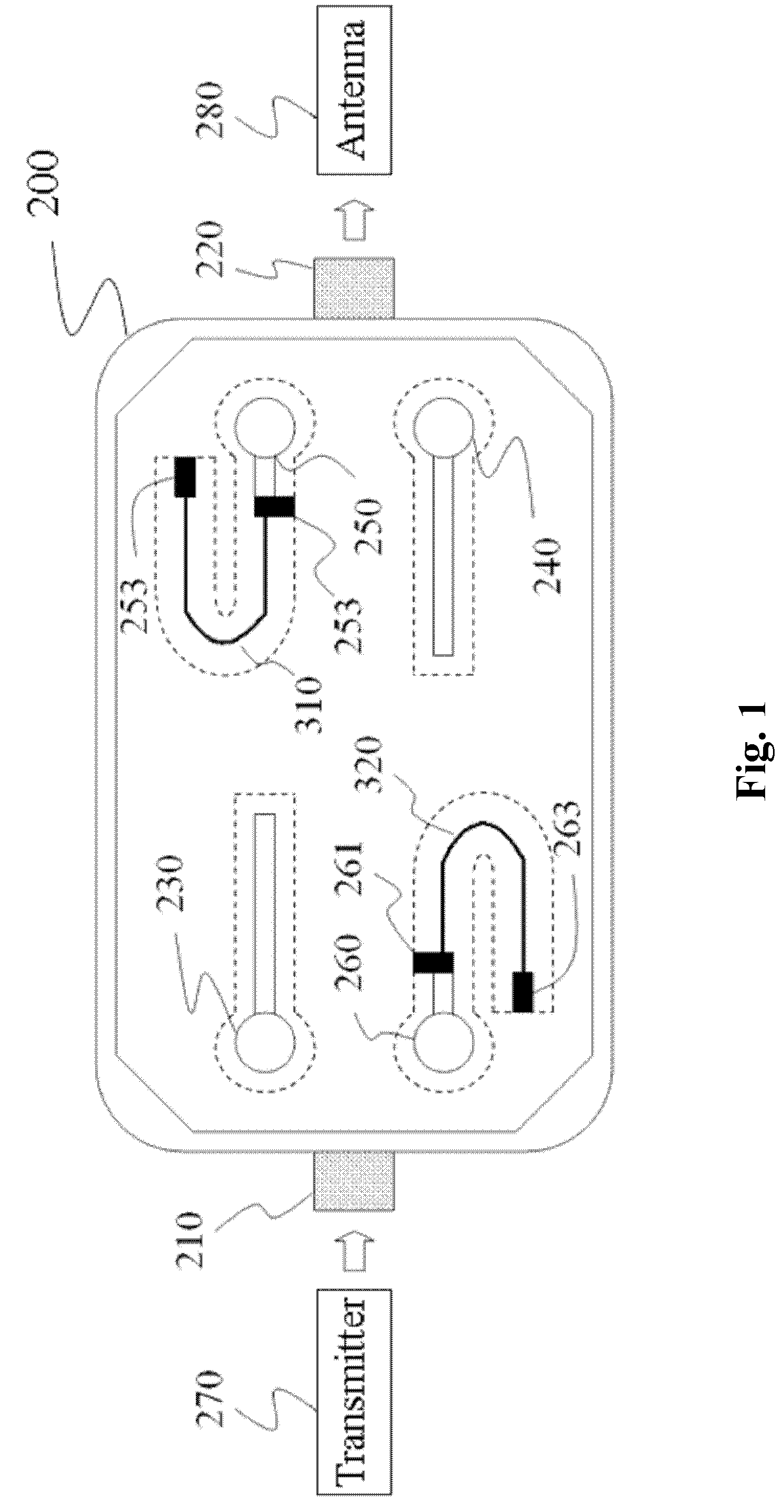
[0016]An embodiment of a bi-directional coupler of the present disclosure uses improved terminal circuits to reduce return loss and enhance isolation for resistors and achieve high directivity of the bi-directional coupler. In other words, two terminal resistors, which are separated by a transmission line replace a terminal resistor residing in a conventional terminal circuit. Therefore, resistance tolerance influence caused by manufacturing processes and temperature variations and parasitical effect influence from parasitical capacitors is minimized, thereby enhancing accuracy of terminal circuits of the bi-directional coupler.
[0017]FIG. 1 shows...
PUM
 Abstract
Description
Claims
Application Information
 - R&D
- Intellectual Property
- Life Sciences
- Materials
- Tech Scout
- Unparalleled Data Quality
- Higher Quality Content
- 60% Fewer Hallucinations
Browse by: Latest US Patents, China's latest patents, Technical Efficacy Thesaurus, Application Domain, Technology Topic, Popular Technical Reports.
© 2025 PatSnap. All rights reserved.Legal|Privacy policy|Modern Slavery Act Transparency Statement|Sitemap|About US| Contact US: help@patsnap.com