Electromechanical adjusting instrument

a technology of adjusting instruments and electric motors, applied in the field of adjusting instruments and methods, can solve the problems of musculoskeletal discomfort and a variety of related symptoms, and each of the referenced items suffers, and cannot use more than one electric power source to provide reproducible impulse energy to the body

Active Publication Date: 2014-02-04
COLLOCA CHRISTOPHER J +1
View PDF11 Cites 8 Cited by
  • Summary
  • Abstract
  • Description
  • Claims
  • Application Information

AI Technical Summary

Benefits of technology

[0013]It is an object of the present invention to provide a chiropractic adjusting instrument comprising a housing having an opening; a thrust nose piece movable mounted in the housing and comprising a preload side and an outer end including an outer end shank for coupline to at least one impact head wherein the opening allows the coupled outer end shank impact head to contact a body; a preload switch plunger coupled to the preload end of the thrust nose piece; a dampening spring interposed between the housing and the outer end of the thrust nose piece or a first inner housing stop having a first passage to accept the thrust nose piece; a solenoid mounted in the housing and comprising: a longitudinal axis and a core having a third passage to accept the preload switch plunger so that the core is movable along the longitudinal axis and is in alignment with the thrust nose piece; a preload spring interposed between the preload side of the thrust nose piece and a second inner housing stop having a second passage sufficient to accept the coupled preload switch plunger preload side; a recoil spring interposed between the core and the coupled preload switch plunger preload end; a third inner stop to prevent the normal urging of core away from the coupled preload switch plunger preload end and having a fourth inner passage to accept the preload switch plunger; a pulse system operatively connected to a power source to provide alternating current for energizing the solenoids to impart impulse energy from the core to the thrust nose piece which is reproducible independent of the power source; a trigger system for triggering the pulse system comprising a switch activated by the preload switch plunger. Additionally, in a preferred embodiment, a sensing device may be used to provide control. More preferably, the sensing device may be coupled to the nose piece. Most preferably, the sensing device is an accelerometer, a load cell or an impedance head, wherein the impedance head may preferably comprise the combination of an accelerometer and a load cell.

Problems solved by technology

Misalignment or other mis-adjustment or subluxation of the spine and bones of the human body can lead to musculoskeletal discomfort and a variety of related symptoms.
Each one of these referenced items, however, suffers from disadvantages including, for example, one or more of the following.
One disadvantage is that they are not able to use more than one electric power source to provide reproducible impulse energy to the body.
Another disadvantage is that they do not have trigger system and pulse system including an interlock such that the device cannot be activated with an appropriate preload.
Another disadvantage is that they do not have a way to use the electric impulses applied to the solenoid to calibrate the instrument and to diagnose the electric impulses applied to the solenoid.
Another disadvantage is that they do not have an interlock so that the device cannot be triggered unless the appropriate preload is attained.
Another disadvantage is that they do not create adjusting instruments that have a waveform specifically tuned to the nature of the body to allow more bone movement and more neural receptor stimulation with less force.
Another disadvantage is that they do not provide a thrust nose piece to accept interchangeable impact heads or reduce vibrations to the operator to provide comfort.
Another disadvantage is that they do not have a preload indication system.

Method used


Image

  • Electromechanical adjusting instrument
  • Electromechanical adjusting instrument
  • Electromechanical adjusting instrument

Examples


Embodiment Construction

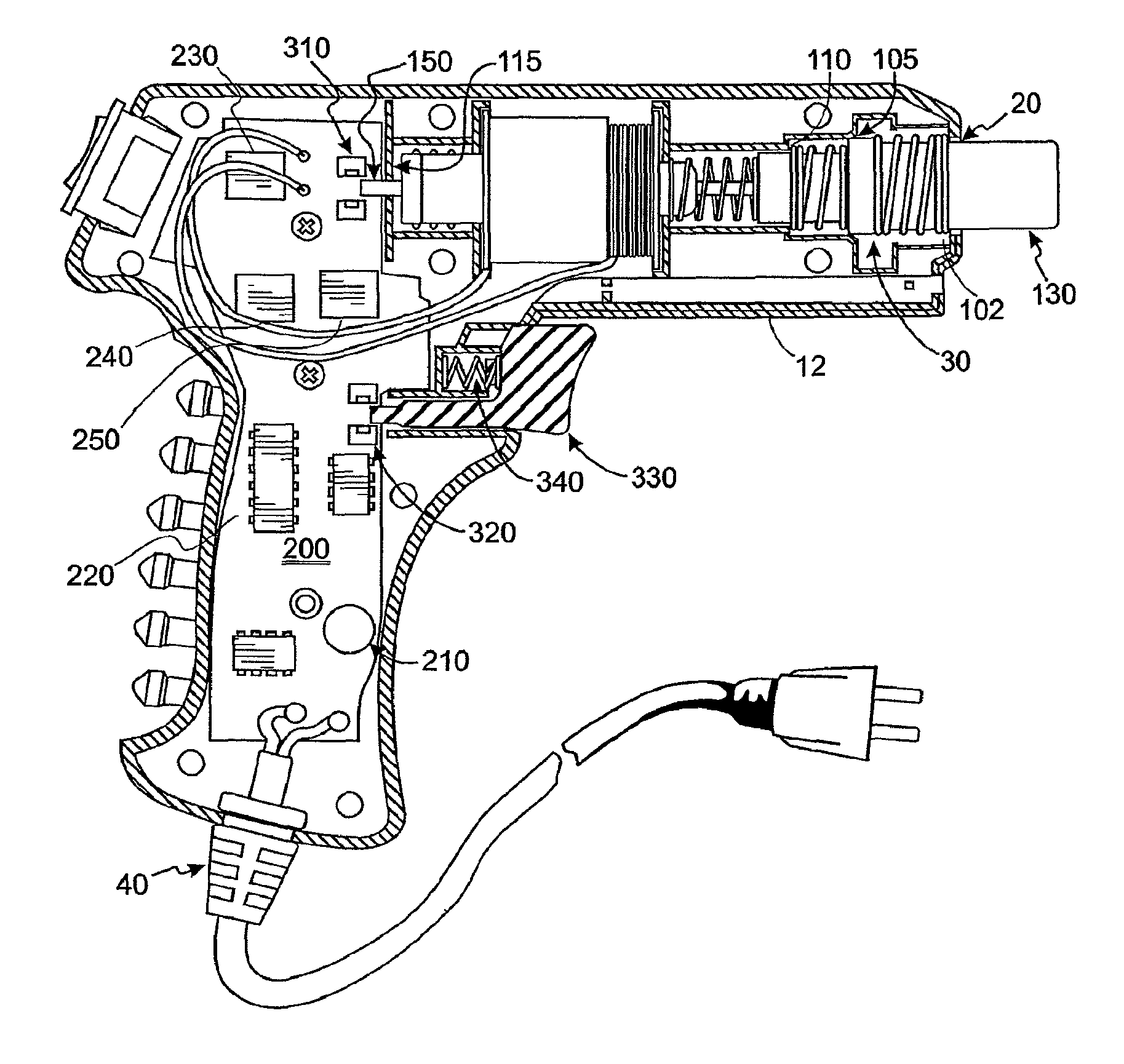
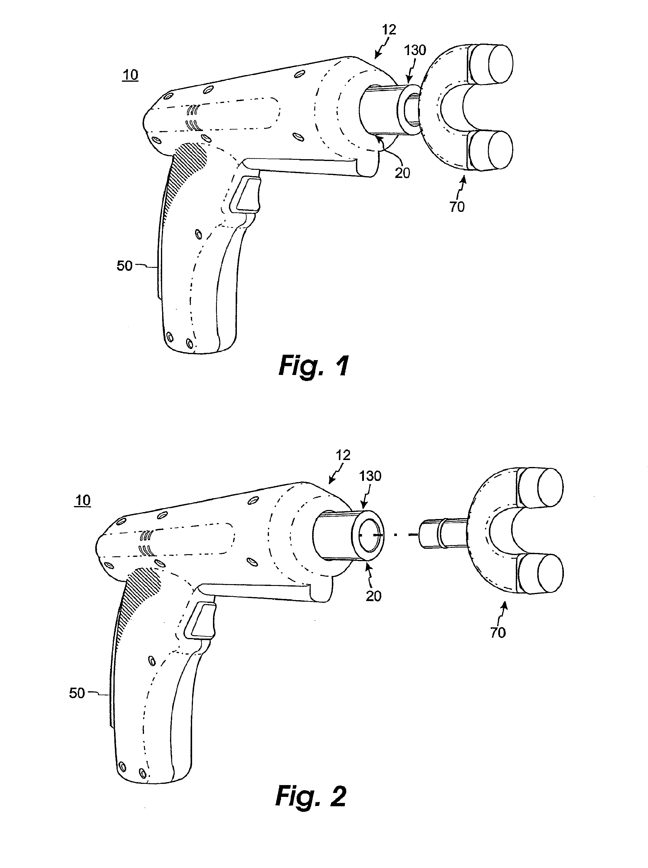
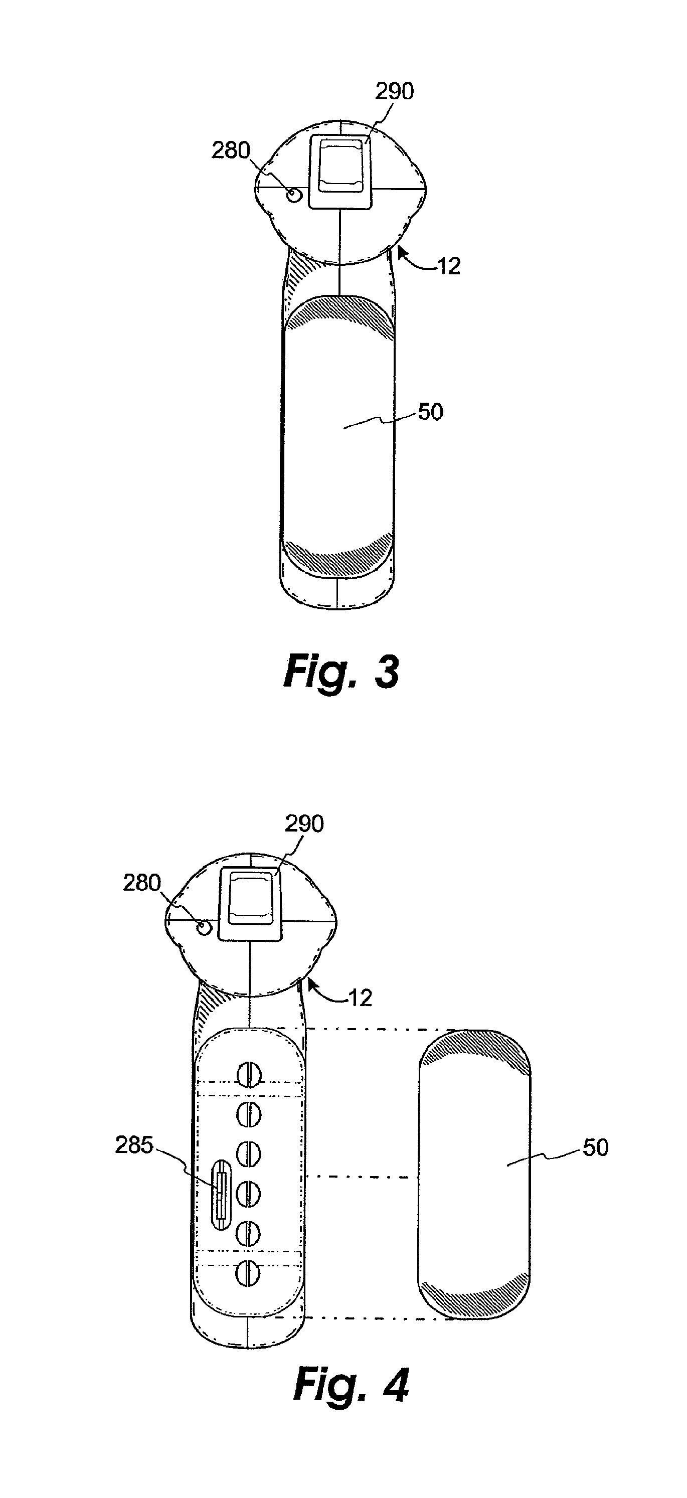
[0033]Referring to the FIGS. 1-13 and 14A-D, there are depicted preferred embodiments of the chiropractic adjusting instrument invention and its components. The preferred embodiment of the invention, generally referenced by 10, is depicted in FIGS. 1-6 and include a housing 12 that, in this preferred embodiment, is gun shaped having an alternating current power cord 40 and a shock absorbing grip 50. The chiropractic adjusting instrument 10 further includes an electromechanical drive mechanism 100, an electronic pulse system 200 and a trigger system.

[0034]In the preferred embodiment, the housing 12 of the chiropractic adjusting instrument 10 has an opening 20 and an inside cavity 30 for mounting the electromechanical drive mechanism 100. Preferably, the housing is made of a non-conductive material such as plastic. As shown in preferred embodiment of FIG. 7, the inside cavity consists of a housing inside 102, a first inner housing stop 105, a second inner housing stop 110 and a third ...


PUM


Abstract

A chiropractic adjusting instrument comprising a housing; thrust nose piece an impact head to contact a body, a preload switch plunger; a dampening spring; a solenoid having a core; a preload spring; a recoil spring; an electronic pulse system operatively connected to a power source to provide alternating current for energizing the solenoid to impart impulse energy from the core to the thrust nose piece which is reproducible and independent of the power source; and a trigger system for triggering the electronic pulse system comprising a switch activated by the preload switch plunger. Preferably, the chiropractic adjusting instrument includes one or more of the following: an intelligent universal AC power converter; optimized force-time waveform; pulse mode operation; a sensing device having a sense output and a suite of electromechanical components designed to promote reproducible dynamic force impulses and safe operation.

Description

[0001]This application is a divisional of prior application Ser. No. 11 / 567,007 filed Dec. 5, 2006, now issued as U.S. Pat. No. 8,083,699, which is herein incorporated by reference, and which claims benefit of U.S. Provisional Application No. 60 / 779,785 filed Mar. 7, 2006 and which is also a continuation-in-part of U.S. application Ser. No. 11 / 162,067 filed Aug. 26, 2005, now issued as U.S. Pat. No. 7,144,417, which claims benefit of U.S. provisional application Nos. 60 / 604,787 filed Aug. 26, 2004 and 60 / 604,738 filed Aug. 26, 2004.FIELD OF THE INVENTION[0002]The present invention relates to the field of adjusting instruments and methods. Particularly, it involves the field of electromechanical manipulation / adjusting instruments used to apply controlled dynamic forces to the human body. More particularly, the invention has an improved force-time waveform and a sensor-controlled pulse mode.BACKGROUND OF THE INVENTION[0003]It is well known in the chiropractic art that humans may suffe...

Claims


Application Information

Patent Timeline
Patent Type & Authority Patents(United States)
IPC IPC(8): A61H1/00A61H23/02
CPCA61H2201/1685H01F7/16A61H23/0218A61H1/008A61H7/005A61H1/0292A61H2201/5084A61H1/005A61H23/02A61H39/04A61H2201/1207A61H2230/65A61H2230/80
Inventor COLLOCA, CHRISTOPHER J.KELLER, TONY S.
Owner COLLOCA CHRISTOPHER J
Why Eureka
Try Eureka