
Inkjet image recorder and method for correction of belt conveyance

a belt conveyancing and image recording technology, applied in the field of inkjet image recording and correction of belt conveyancing, can solve problems such as uneven printing, and achieve the effects of accurate recording, efficient calculation process, and reducing adjustment work tim

Active Publication Date: 2014-02-04
DAINIPPON SCREEN MTG CO LTD
View PDF14 Cites 3 Cited by
  • Summary
  • Abstract
  • Description
  • Claims
  • Application Information

AI Technical Summary

Benefits of technology

The present invention relates to a device for correcting conveyance errors caused by an endless belt. The device performs error correction by calculating the correction amount, adjusting the conveyance rate, and driving the motor. This allows for efficient setting of the range to be corrected and accurate recording of images. The device also includes a marker near the joint of the belt member for precise position alignment and accurate specification of the error-causing region. Additionally, the device monitors the scale added to the endless belt and adjusts the motor driving rate accordingly to maintain a high quality image recording state.

Problems solved by technology

In a system that performs printing while moving a printing material relative to the recording head by the belt conveyance mechanism, a conveyance error of the printing material is one of causes for printing unevenness.

Method used


Image

  • Inkjet image recorder and method for correction of belt conveyance
  • Inkjet image recorder and method for correction of belt conveyance
  • Inkjet image recorder and method for correction of belt conveyance

Examples


Embodiment Construction

[0028]Embodiments of the present invention will hereinafter be described on the basis of the drawings. FIG. 1 is a schematic front view of an inkjet image recorder according to the present invention, and FIG. 2 is a perspective view of it.

[0029]The inkjet image recorder is one that records an image on a long-sized or plate-like recording material S by moving the recording material S in a sub scanning direction indicated by a symbol A or B in FIGS. 1 and 2, and also using a recording head moving mechanism 30 to move a recording head 10 in a main scanning direction that is indicated by a symbol C in FIG. 2 and orthogonal to the sub scanning direction. Note that FIGS. 1 and 2 illustrate a state where an image is recorded on the long-sized roll-like recording material S.

[0030]Referring to FIG. 1, a porous (so-called mesh material) endless belt 51 is wound on a pair of rollers 53 and 54. Note that the pair of rollers 53 and 54 and the endless belt 51 constitute a belt conveyance mechanis...


PUM


Abstract

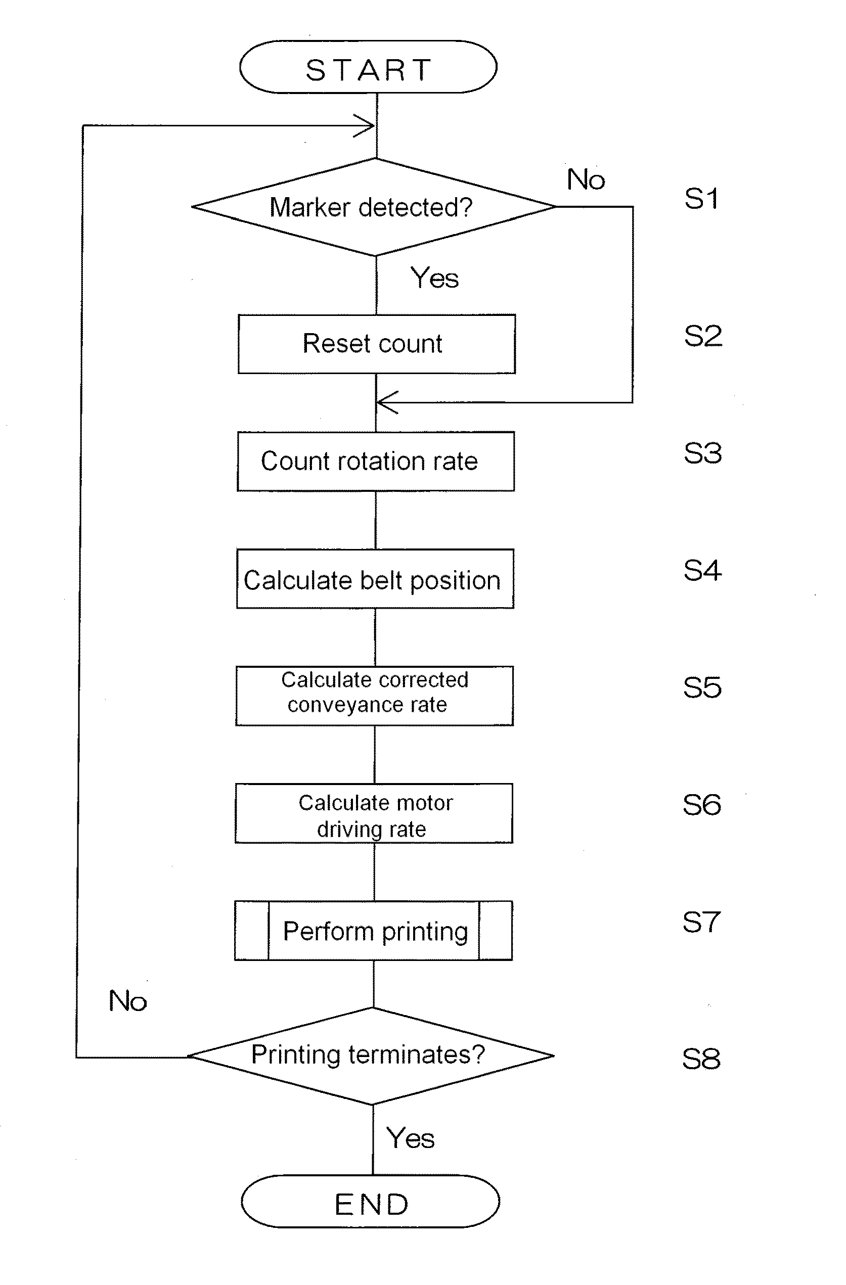
Provided are an ink-jet image recorder for recording an image precisely and a method for correction of belt conveyance mechanisms by controlling the roller drive on the basis of fluctuation of the conveyance rate caused by a particular failure in the endless belt. In the belt conveyor mechanism of the ink-jet image recorder, the method for correction of the belt conveyance comprises a position detection step (Step S1) for detecting a specified position on the endless belt; a measurement step for measuring the rotation rate of the roller; a position calculation step (Step S4) for specifying a position on the endless belt; a calculation step (Step S5) for calculating the corrected conveyance rate; in the error-causing region where a conveyance error is caused by the endless belt during movement of the endless belt, by addition to the position of the endless belt, of the amount of correction of the conveyance rate of the endless belt calculated from the conveyance error corresponding to the error-causing region; and a driving rate calculation step (Step S6) for adjusting the motor driving rate in accordance with the corrected conveyance rate.

Description

CROSS REFERENCE TO RELATED APPLICATIONS[0001]The present application is a 35 U.S.C. §371 national phase conversion of PCT / JP2010 / 060526 filed Jun. 22, 2010 and claims priority of JP2009-223579 filed Sep. 29, 2009, both incorporated herein in their entirety.TECHNICAL FIELD[0002]The present invention relates to an inkjet image recorder that records an image on a recording material by, in main and sub scanning directions, relatively moving the recording material conveyed by a belt conveyance mechanism and a recording head.BACKGROUND ART[0003]In such an inkjet image recorder, as a conveyance mechanism for a printing material, there is employed a belt conveyance mechanism that conveys a recording material in a direction orthogonal to a moving direction of a recording head by, in a state where the recording material is sucked and held on an endless belt wound on a pair of rollers including a driving motor and a driven motor, driving the driving roller.[0004]In a system that performs print...

Claims


Application Information

Patent Timeline
Patent Type & Authority Patents(United States)
IPC IPC(8): B41J29/393
CPCB65H2513/106B65H2404/285B41J11/42B65H2511/20B41J11/007B65H2513/10B65H20/08B41J15/04B65H2220/02B65H2220/11B65H2220/03
Inventor SHIMIZU, KEIGOTAHARA, TATSUKI
Owner DAINIPPON SCREEN MTG CO LTD
Learn More