
Method for beamforming transmissions from a network element having a plurality of antennas, and the network element

a network element and antenna technology, applied in the field of wireless communication systems, can solve the problems of rapid channel state estimation and scaling, and achieve the effect of increasing the received signal strength

Active Publication Date: 2014-01-07
ALCATEL LUCENT SAS
View PDF14 Cites 2 Cited by
  • Summary
  • Abstract
  • Description
  • Claims
  • Application Information

AI Technical Summary

Benefits of technology

[0014]In one embodiment, the beamforming increases received signal strength at the terminal coherently.
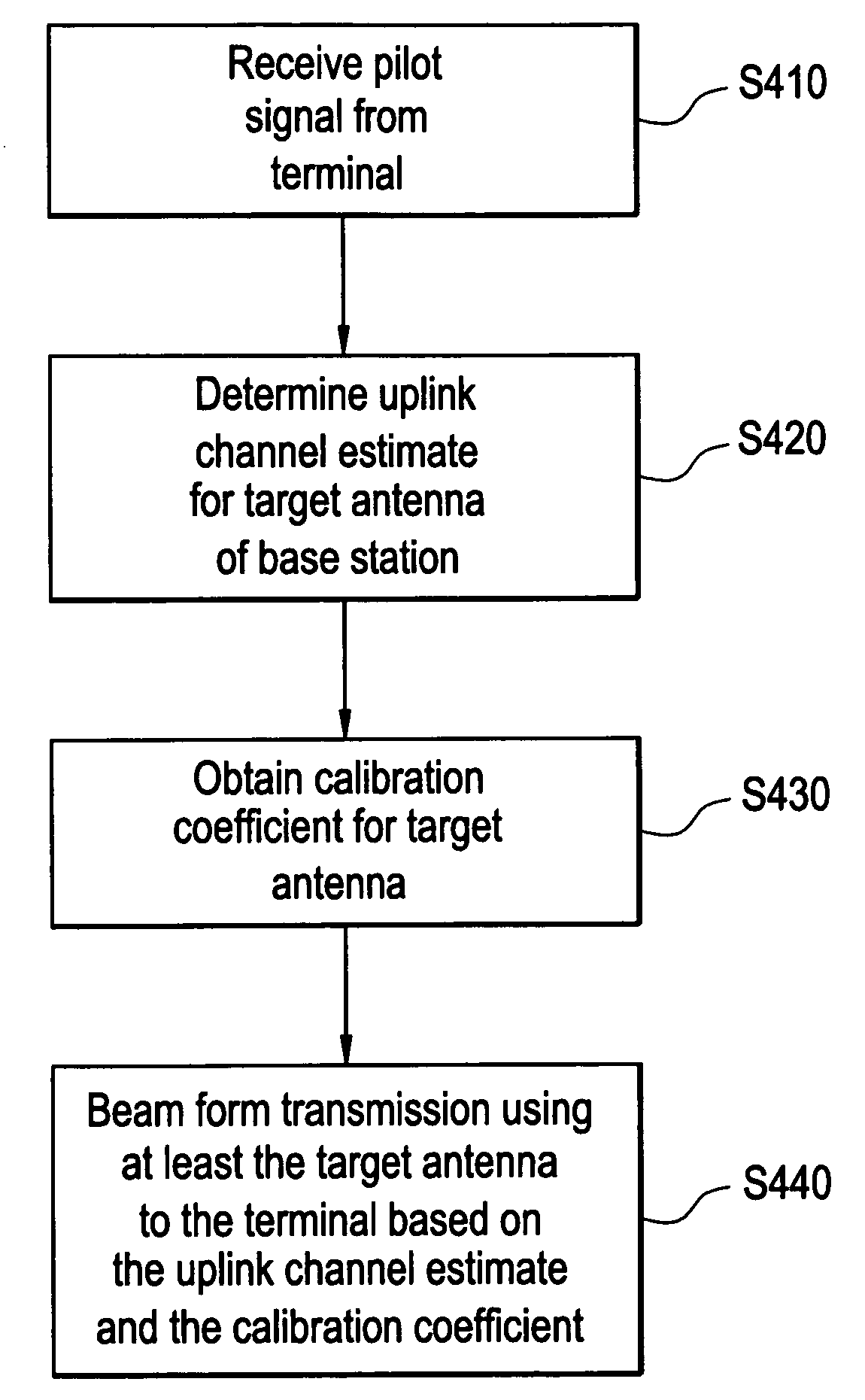
[0015]In another embodiment, the beamforming includes removing phase error in beamforming the transmission. For example, the beamforming may determine a calibration constant based on a frequency response of transmission and reception sides associated with the target antenna, and the beamforming removes the phase error based on the calibration coefficient.

Problems solved by technology

One technical challenge is rapid channel state estimation.
However, for the M downlink channels, the base station may have to send M pilots.
Scaling is therefore a problem in this system.

Method used


Image

  • Method for beamforming transmissions from a network element having a plurality of antennas, and the network element
  • Method for beamforming transmissions from a network element having a plurality of antennas, and the network element
  • Method for beamforming transmissions from a network element having a plurality of antennas, and the network element

Examples


Embodiment Construction

[0024]Various example embodiments will now be described more fully with reference to the accompanying drawings in which some example embodiments are shown.

[0025]While example embodiments are capable of various modifications and alternative forms, the embodiments are shown by way of example in the drawings and will be described herein in detail. It should be understood, however, that there is no intent to limit example embodiments to the particular forms disclosed. On the contrary, example embodiments are to cover all modifications, equivalents, and alternatives falling within the scope of this disclosure. Like numbers refer to like elements throughout the description of the figures.

[0026]Although the terms first, second, etc. may be used herein to describe various elements, these elements should not be limited by these terms. These terms are only used to distinguish one element from another. For example, a first element could be termed second element, and similarly, a second element...


PUM


Abstract

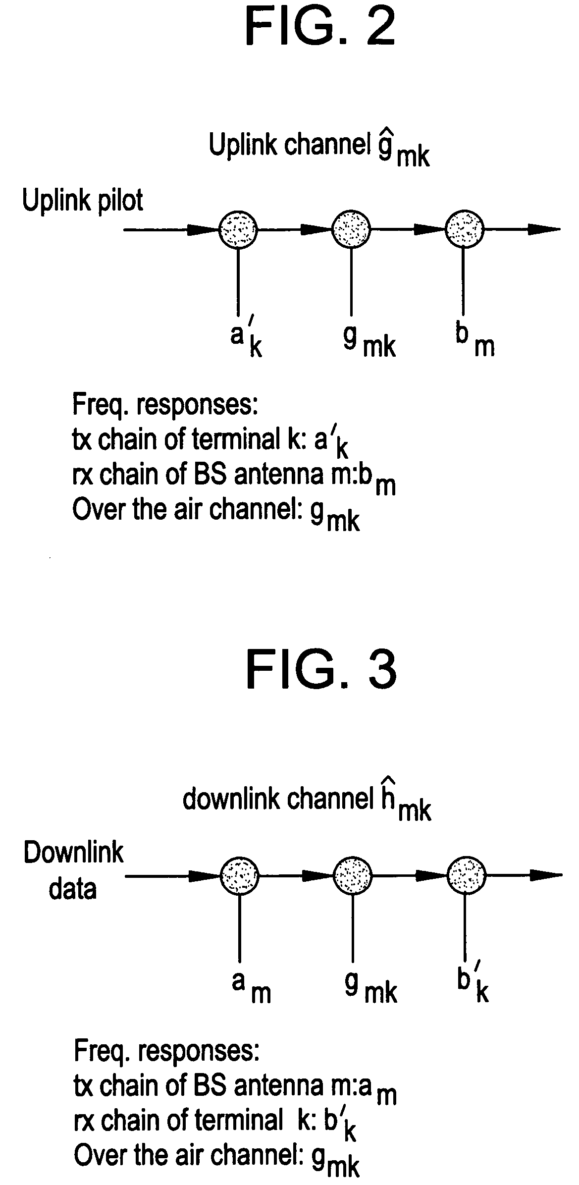
In one embodiment, the method includes receiving a pilot signal from a terminal at a target antenna of the plurality of antennas of the network element, determining an uplink channel estimate for the target antenna based on the received pilot signal, and obtaining a calibration coefficient associated with the target antenna. The calibration coefficient is based on a channel estimate between the target antenna and a different one of the plurality of antennas. The method further includes beamforming a transmission to the terminal using at least the target antenna based on the determined uplink channel estimate and the obtained calibration coefficient.

Description

BACKGROUND OF THE INVENTION[0001]In wireless communication systems, base stations are traditionally equipped with a small number of antennas. A radically different approach involves base stations with an unprecedented numbers of antennas (M) simultaneously serving a much smaller number of mobile terminals (K where M>>K) using multi-user beamforming. Operating with a large ratio of antennas to terminals under simultaneous service can yield large increases in both spectral efficiency and energy efficiency. As the number of service antennas increases and power is reduced the most simple signal processing, conjugate beamforming on the forward link and matched-filtering on the reverse link, asymptotically achieves near-optimal performance. One technical challenge is rapid channel state estimation.[0002]With M base station antennas and K terminals, a large antenna array (LSAS) base station deals with 2M×K channels. For each terminal, the base station can get all M uplink channels wi...

Claims


Application Information

Patent Timeline
Patent Type & Authority Patents(United States)
IPC IPC(8): H04L25/03H04L25/49H04K1/02
CPCH04B17/0012H04B7/0452H04B7/0617H04B17/14
Inventor LI, LIMARZETTA, THOMAS
Owner ALCATEL LUCENT SAS
Learn More