Switching control circuit and switching power-supply apparatus
a control circuit and power supply technology, applied in the direction of power conversion systems, instruments, dc-dc conversion, etc., can solve the problems of increasing increasing the unit price of the ic, and limiting the number of functions that can be provided, so as to reduce the number of terminals of the ic, reduce the size of the ic, and reduce the cost
- Summary
- Abstract
- Description
- Claims
- Application Information
AI Technical Summary
Benefits of technology
Problems solved by technology
Method used
Image
Examples
first preferred embodiment
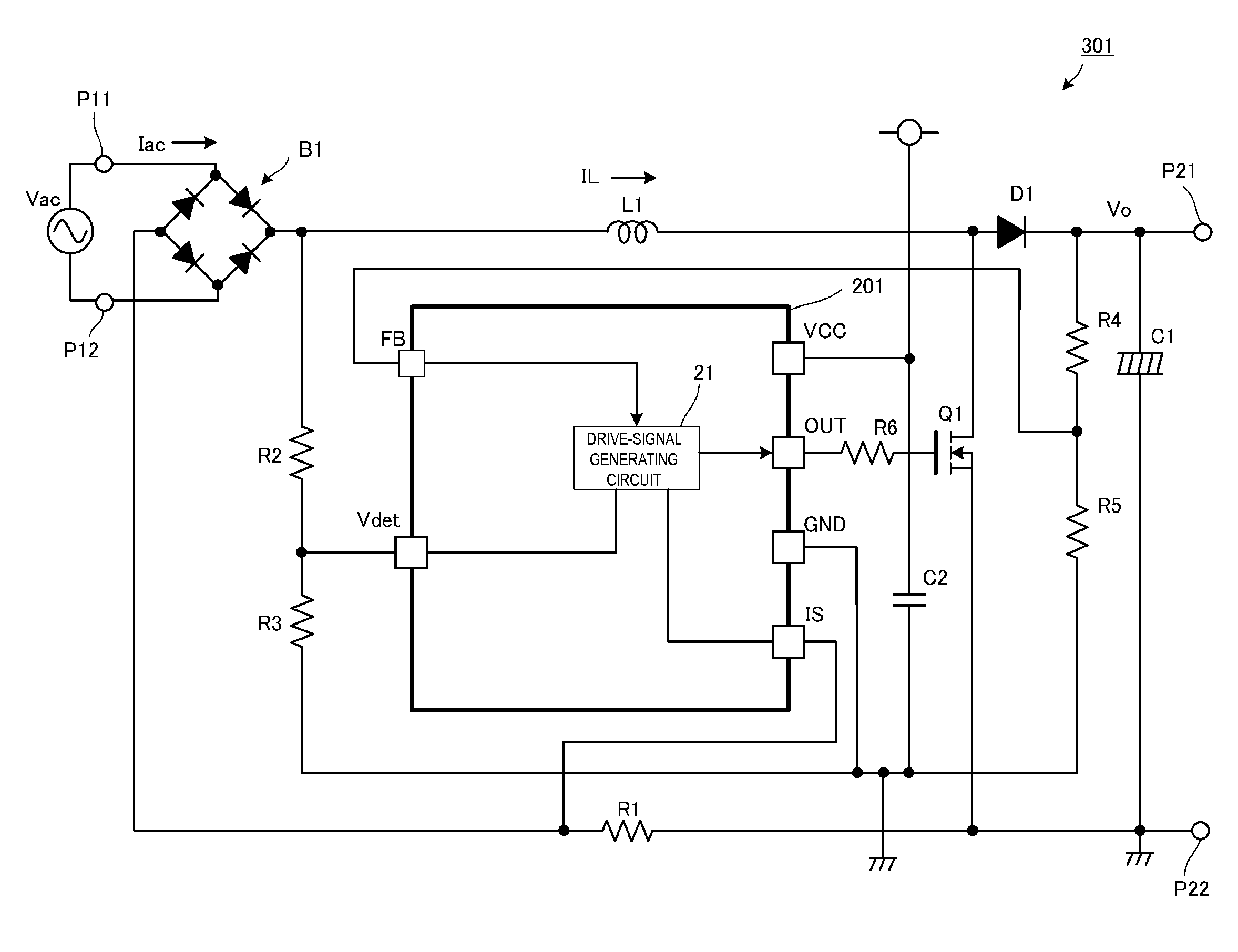
[0075]FIG. 2 is a circuit diagram of a PFC (power-factor corrected) converter 301 according to a first preferred embodiment of the present invention.
[0076]The PFC converter 301 is one example of a switching control device according to a preferred embodiment of the present invention and includes a switching control integrated circuit (IC) 201 corresponding to the switching control circuit of a preferred embodiment of the present invention.
[0077]The PFC converter 301 includes input terminals P11 and P12 and output terminals P21 and P22. An alternating-current (AC) input power supply Vac, which is commercial AC power supply, is preferably input to the input terminals P11 and P12 and a load circuit is connected to the output terminals P21 and P22.
[0078]Examples of the load circuit include a DC-DC converter or a circuit of electronic equipment that receives a power supply through a DC-DC converter.
[0079]An input stage of the PFC converter 301 includes a diode bridge B1, which functions a...
second preferred embodiment
[0094]FIG. 5 is a circuit diagram of a DC-DC converter 302 according to a second preferred embodiment of the present invention.
[0095]The DC-DC converter 302 is one example of the switching control device according to a preferred embodiment of the present invention and includes a switching control IC 202 corresponding to the switching control circuit according to a preferred embodiment of the present invention.
[0096]A voltage of the DC input power supply Vi is input between an input terminal PI(+) and an input terminal PI(G) of the DC-DC converter 302. A load is connected between an output terminal PO(+) and an output terminal PO(G) of the DC-DC converter 302. A predetermined DC voltage is output to the load.
[0097]A first series circuit including a capacitor Cr, an inductor Lr, a primary winding np of a transformer T, a first switching element Q1, and a current-detection resistor R7 that are connected in series is preferably provided between the input terminal PI(+) and the input ter...
third preferred embodiment
[0125]FIG. 9 is a block diagram showing an internal configuration of a switching control IC 200 included in a DC-DC converter according to a third preferred embodiment of the present invention.
[0126]In FIG. 9, when the standby mode is on, a maximum-blanking-frequency setting circuit 230 preferably sets a maximum blanking frequency in accordance with a voltage of a feedback terminal FB (a hidden function of ON / OFF of the standby mode is accomplished at a ZT terminal described below). The maximum-blanking-frequency setting circuit 230 also reads the voltage of the feedback terminal FB when the converter is started. Now, a description will be given of a case in which the read voltage value is less than or equal to a predetermined value.
[0127]Based on the voltage at the ZT terminal, a ZT-voltage detection circuit226 detects that the voltage across the drive winding nb of the transformer T is reversed and issues a trigger to a one-shot circuit 240. The maximum-blanking-frequency setting ...
PUM
 Abstract
Description
Claims
Application Information
 - R&D
- Intellectual Property
- Life Sciences
- Materials
- Tech Scout
- Unparalleled Data Quality
- Higher Quality Content
- 60% Fewer Hallucinations
Browse by: Latest US Patents, China's latest patents, Technical Efficacy Thesaurus, Application Domain, Technology Topic, Popular Technical Reports.
© 2025 PatSnap. All rights reserved.Legal|Privacy policy|Modern Slavery Act Transparency Statement|Sitemap|About US| Contact US: help@patsnap.com


