
Vacuum processing chambers incorporating a moveable flow equalizer

a technology of vacuum processing chamber and equalizer, which is applied in the field of vacuum processing chamber, can solve problems such as limiting process uniformity, and achieve the effect of reducing or eliminating cross-talk

Inactive Publication Date: 2013-12-31
APPLIED MATERIALS INC
View PDF76 Cites 27 Cited by
  • Summary
  • Abstract
  • Description
  • Claims
  • Application Information

AI Technical Summary

Benefits of technology

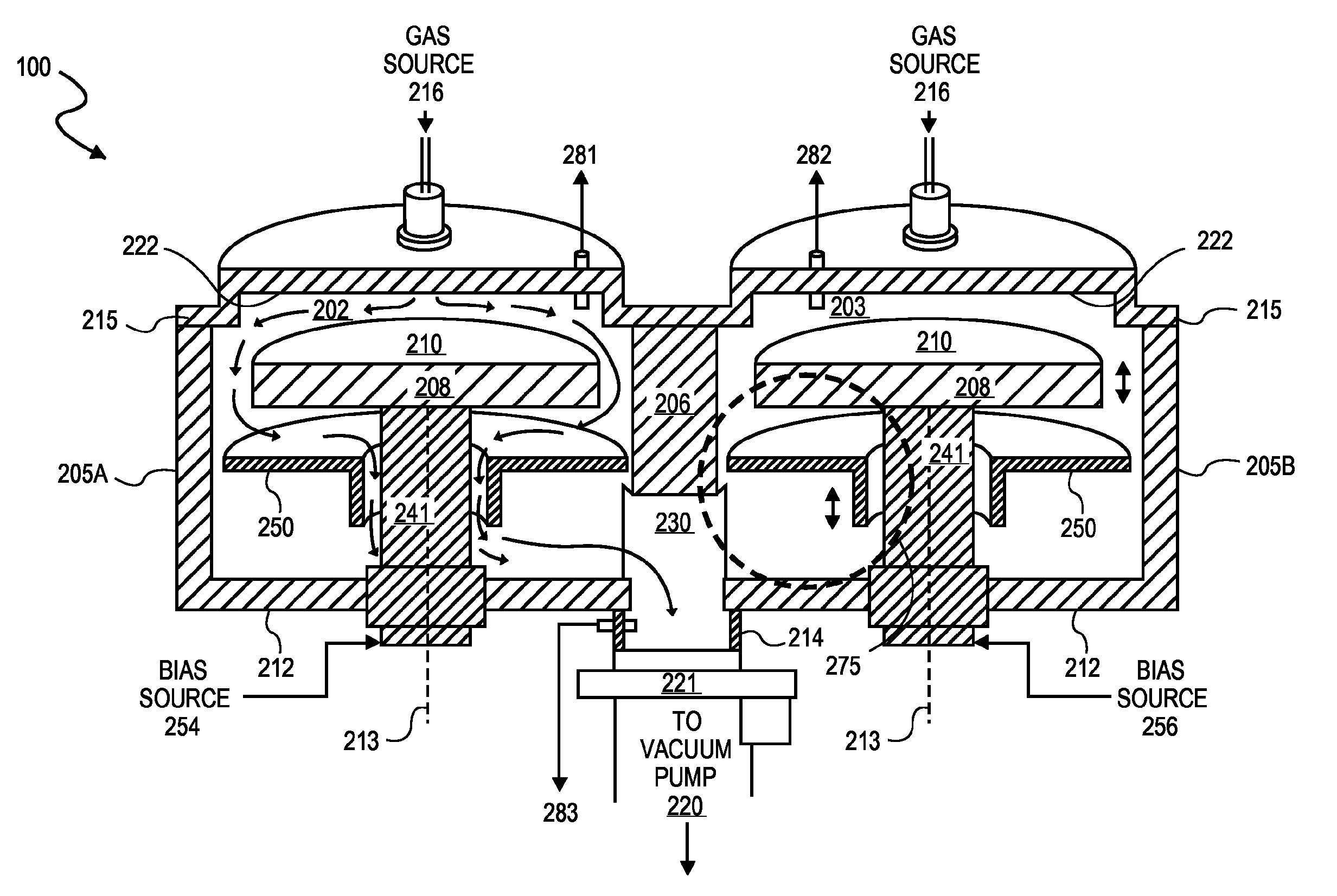
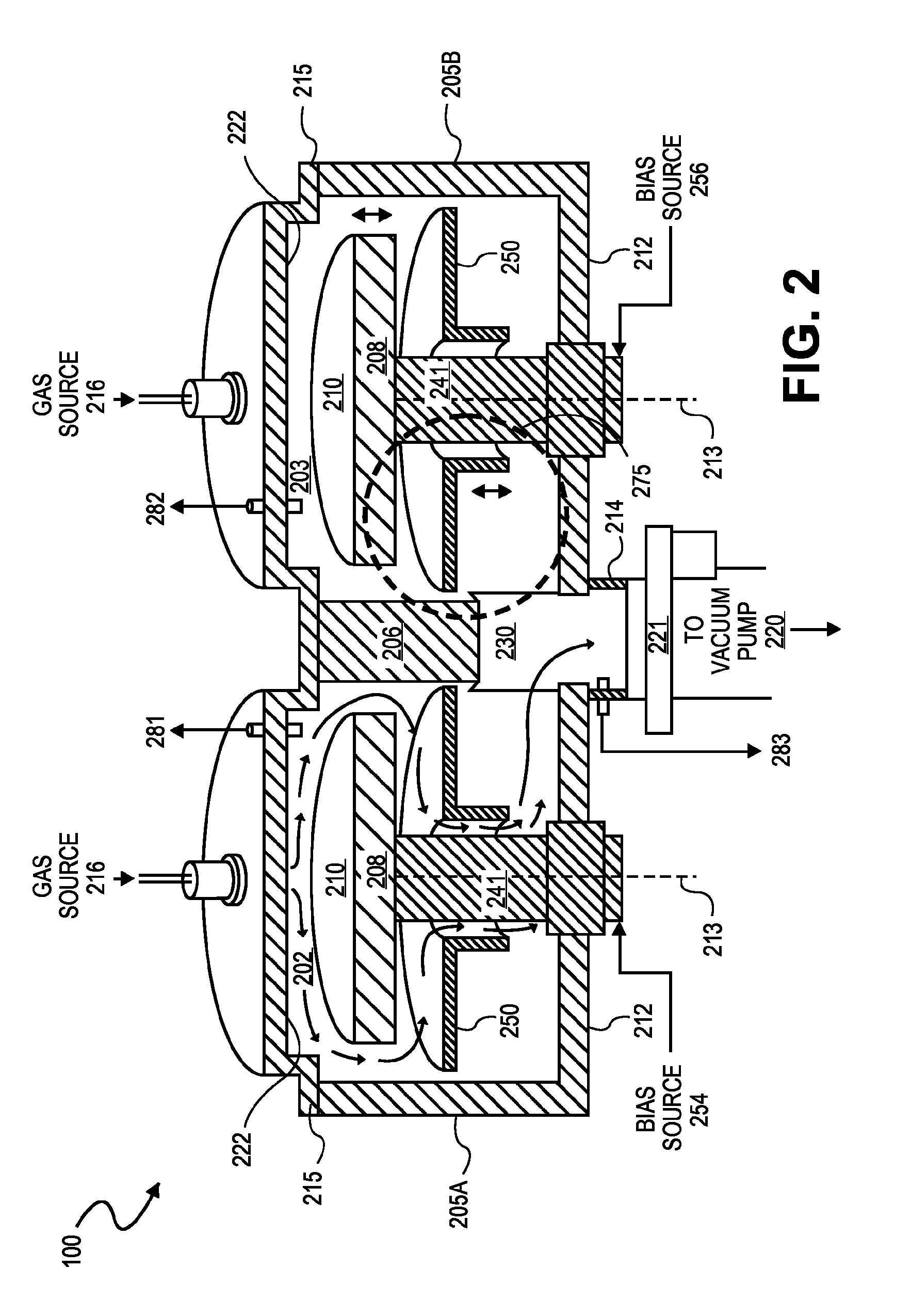
The patent describes an apparatus for vacuum processing of a workpiece that includes two tandem chambers that share a vacuum pump. Each chamber has its own flow equalizer to control the process pressure independently. This helps to reduce or eliminate cross-talk between the chambers. The technical effect of this is that it allows for better control and precision during vacuum processing of the workpiece.

Problems solved by technology

Conductance asymmetry may limit process uniformity to as low as 10% across the workpiece.

Method used


Image

  • Vacuum processing chambers incorporating a moveable flow equalizer
  • Vacuum processing chambers incorporating a moveable flow equalizer
  • Vacuum processing chambers incorporating a moveable flow equalizer

Examples


Embodiment Construction

[0018]Embodiments of are described herein with reference to figures. However, particular embodiments may be practiced without one or more of these specific details, or in combination with other known methods, materials, and apparatuses. In the following description, numerous specific details are set forth, such as specific materials, dimensions and processes parameters etc. to provide a thorough understanding of the present invention. In other instances, well-known equipment design and process control techniques have not been described in particular detail to avoid unnecessarily obscuring the present invention. Reference throughout this specification to “an embodiment” means that a particular feature, structure, material, or characteristic described in connection with the embodiment is included in at least one embodiment of the invention. Thus, the appearances of the phrase “in an embodiment” in various places throughout this specification are not necessarily referring to the same e...


PUM

PropertyMeasurementUnit
radial lengthaaaaaaaaaa

Abstract

A method and apparatus for vacuum processing of a workpiece, the apparatus including a flow equalizer disposed in a vacuum processing chamber between a workpiece support pedestal and a pump port located in a wall of the vacuum processing chamber. In an embodiment, the flow equalizer has a first annular surface concentric about the workpiece support pedestal to provide conductance symmetry about the workpiece support even when the pump port is asymmetrically positioned within the vacuum processing chamber. In an embodiment, the flow equalizer has a second annular surface facing a lower surface of the workpiece support pedestal to restrict conductance as the flow equalizer is moved is response to a chamber pressure control signal. In an embodiment, the apparatus for vacuum processing of a workpiece includes tandem vacuum processing chambers sharing a vacuum pump with each tandem chamber including a flow equalizer to reduce cross-talk between the tandem chambers.

Description

BACKGROUND[0001]1. Field[0002]Embodiments of the present invention relate to the electronics manufacturing industry and more particularly to a vacuum processing apparatus.[0003]2. Discussion of Related Art[0004]Vacuum processing systems are ubiquitous in microelectronics manufacturing. Many vacuum processing systems include a processing chamber designed for processing a workpiece with a plasma discharge. One such chamber generally includes a first and second electrode arranged in a parallel plate configuration. At least one of the electrodes is powered by a generator typically operating at an industrial RF band. Each electrode is typically a planar, circular disc to be substantially the same shape, albeit of a larger diameter, as a workpiece to be processed (e.g., a semiconductor wafer). It is conventional to pump down the processing chamber to sub-atmospheric pressures (i.e., vacuum) using a vacuum pump coupled to the chamber via a pump port. A process pressure may be controlled to...

Claims


Application Information

Patent Timeline
Patent Type & Authority Patents(United States)
IPC IPC(8): C23F1/00H01L21/306C23C16/06C23C16/455C23C16/22
CPCH01L21/68785H01J37/32449H01J37/185H01L21/6719H01J2237/182H01J37/3244H01J2237/2001C23C16/4412
Inventor KIM, JISOOLILL, THORSTEN B.
Owner APPLIED MATERIALS INC
Learn More