
Band, wristwatch with the band and method of making the band

a wristwatch and band technology, applied in the field of bands, wristwatches with bands and methods of making bands, can solve the problems of limiting the improvement of band strength, affecting the wear of wristwatches, so as to achieve the effect of increasing strength

Active Publication Date: 2013-12-24
CASIO COMPUTER CO LTD
View PDF18 Cites 46 Cited by
  • Summary
  • Abstract
  • Description
  • Claims
  • Application Information

AI Technical Summary

Benefits of technology

[0009]It is therefore an object of the present invention to provide a band of greatly increased strength where neither breakage of the band nor separation of the component layer from the band due to twisting of the band occurs during its use. The present invention also provides a wristwatch using the band and a method of making the band.
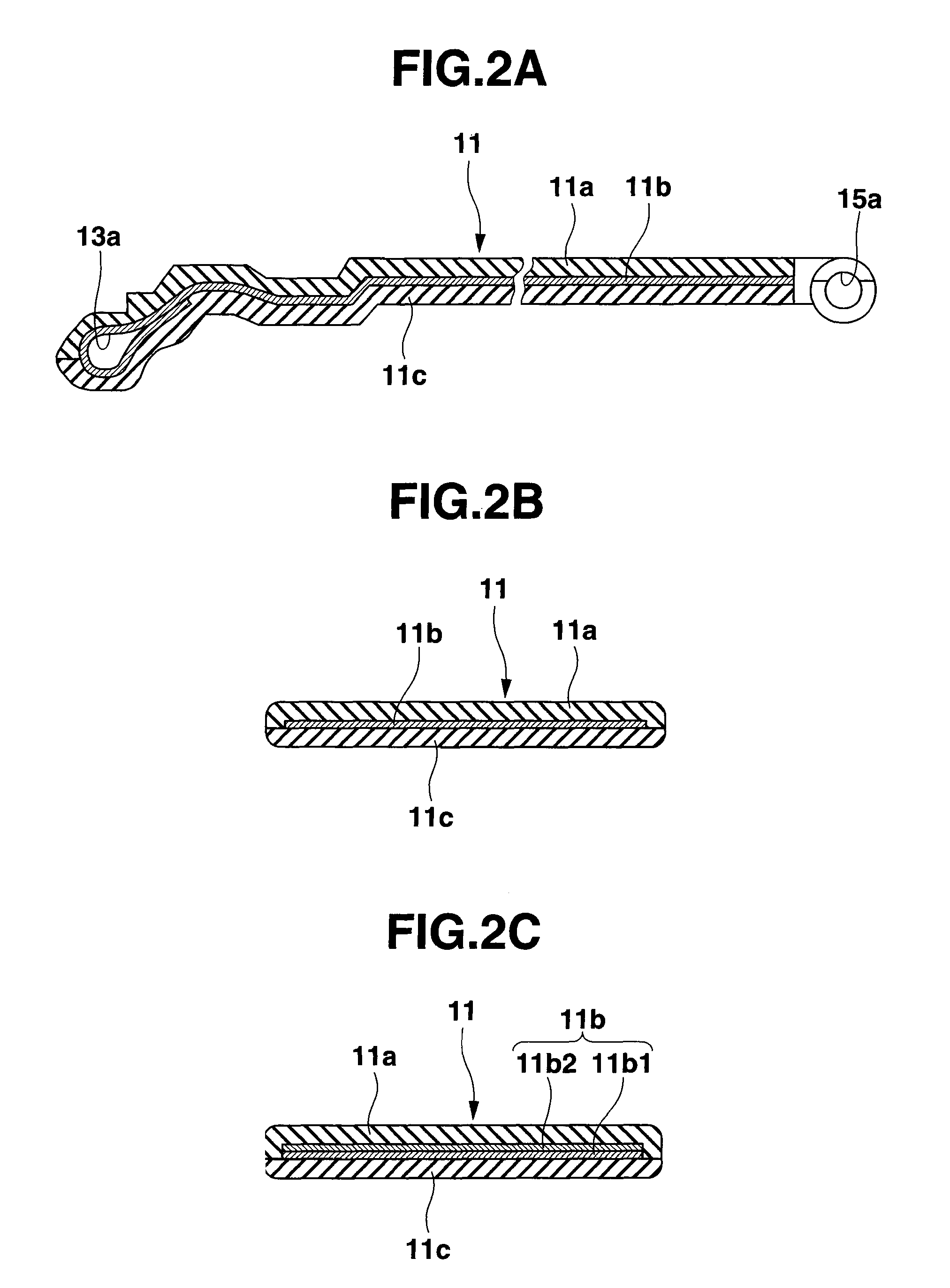
[0027]Thus, according to the band of this invention, a band-shaped support layer includes a fabric of two groups of bundles of one or more kinds of fibers selected from the group of kinds of fibers consisting of carbon fibers, glass fibers, aramid fibers and boron fibers and woven or knit such that the selected two groups of bundles of one or more kinds of fibers extend perpendicular to each other. Further, the selected two groups of one or more kinds of fibers of the support layer extend at the predetermined angle to the longitudinal and transverse directions of the band. Thus, the fibers of the support layer are easy to extend in the longitudinal direction thereof in response to a longitudinal force applied to the support layer, thereby greatly improving the strength of the support layer against longitudinal pulling and / or twisting of the band. Thus, breakage and twisting of the band which are liable to occur during its use and separation between the first and second resin layers due to twisting of the band are prevented.
[0028]Likewise, according to the band making method of this invention, from the large sheet made of two groups of bundles of one or more kinds of fibers selected from the group of kinds of fibers consisting of carbon fibers, glass fibers, aramid fibers and boron fibers and woven or knit such that the selected two groups of bundles of one or more kinds of fibers extend perpendicular to each other, a plurality of band-shaped support layers are cut out such that the support layers extend at the predetermined angle to the extending direction of the fibers of the large sheet. Therefore, cutting out the support layers is performed rapidly and easily. In addition, the first resin layer is caused to adhere closely to one surface of the support layer using the molds and the second resin layer is also caused to adhere closely to the other surface of the support layer using the molds. Thus, a band is made having a beautiful appearance and a sense of high quality.

Problems solved by technology

These bands and loops are liable to be broken when used for a long time because the resin materials are likely to absorb moisture and mold and their function is degraded.
However, only selection of such materials would limit improvements in the band strength.
However, no consideration is given to reinforcement of an end of the band which is connected to the case or, more particularly, of the peripheral part of a through hole extending through the width of the band end portion through which hole a spring bar is inserted to connect the band end portion to the case over the spring bar.
Thus, the problem that the band is likely to be broken at the through hole in the band end portion has not been solved.
In addition, there is another problem that the top coat layer is likely to be separated from the band during its use due to partial breakage or twisting of the band.

Method used


Image

  • Band, wristwatch with the band and method of making the band
  • Band, wristwatch with the band and method of making the band
  • Band, wristwatch with the band and method of making the band

Examples


Embodiment Construction

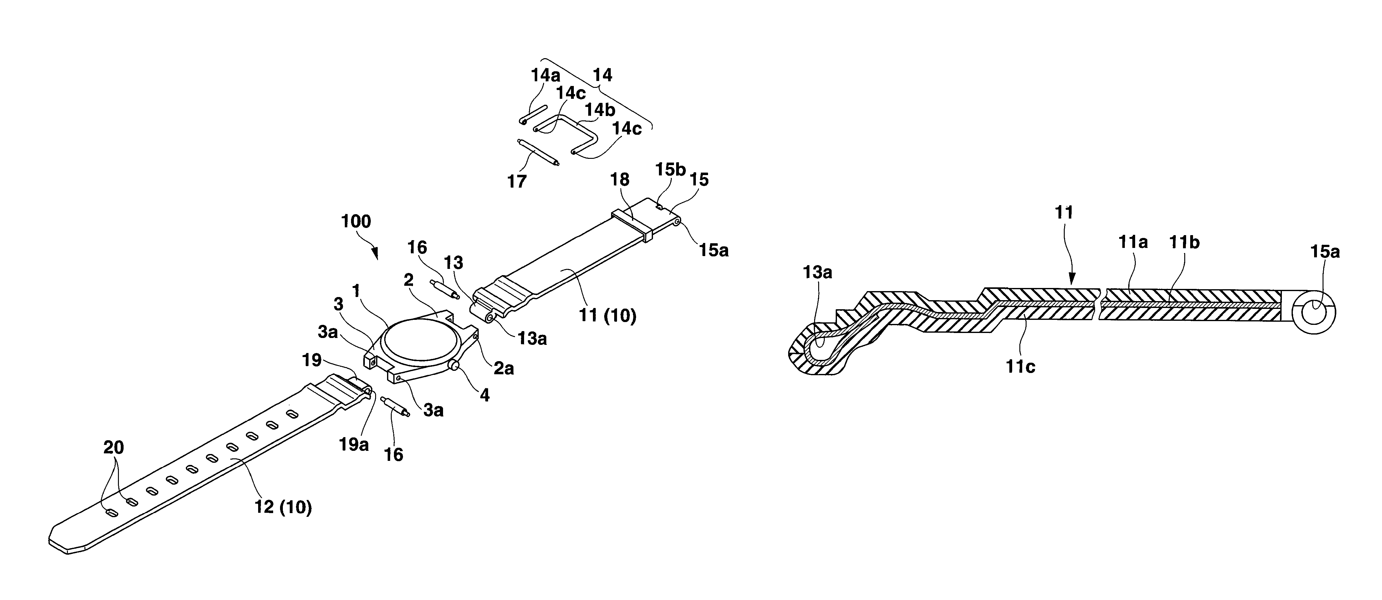
[0050]A preferred embodiment of the present invention will be described with reference to the drawings. FIG. 1 is an exploded perspective view of a wristwatch with a band according to the embodiment. The wristwatch 100 is one which displays time by rotating pointers thereof such as seconds, minute and hour hands (not shown). Of course, it may be a wristwatch with no pointers and / or a wristwatch with both pointers and a liquid crystal time indicator.

[0051]The wristwatch 100 has a case 1 with pairs of band attachment lugs 2, 3. A plurality of operation buttons 4 are provided along the outer periphery of the case 1 to give several commands including time correction although in FIG. 1 only one operation button 4 is shown.

[0052]The band 10 is connected through the pairs of lugs 2 and 3 to the case. In the embodiment the band 10 includes a first band member 11 and a second band member 12. The first band member 11 has a buckle 14 at one end. The buckle 14 is composed of a buckle clasp 14a ...


PUM

PropertyMeasurementUnit
angleaaaaaaaaaa
angleaaaaaaaaaa
angleaaaaaaaaaa

Abstract

A band, a wristwatch with the band and a method of making the band are described. The band includes a strip-like body with a series of holes provided therein along a length thereof for adjusting an effective length thereof. The body includes a band-shaped support layer of woven or knit fabric of bundles of one or more kinds of fibers, the fibers being selected from a group including carbon fibers, glass fibers, aramid fibers and boron fibers. The body also includes a first resin layer adhering closely to one surface of the support layer, and a second resin layer adhering closely to the other surface of the support layer. The fibers of the support layer extend at a predetermined angle to longitudinal and transverse directions of the body.

Description

CROSS-REFERENCE TO RELATED APPLICATIONS[0001]This application is based upon and claims the benefit of priority from prior Japanese Patent Applications No. 2009-201439, filed Sep. 1, 2009; and No. 2010-181370, filed Aug. 13, 2010, the entire contents of both of which are incorporated herein by reference.BACKGROUND OF THE INVENTION[0002]1. Field of the Invention[0003]The present invention relates to a band, a wristwatch with the band and a method of making the band.[0004]2. Description of the Related Art[0005]Recently, wristwatch bands and band retaining loops made of a resin material are used. These bands and loops are liable to be broken when used for a long time because the resin materials are likely to absorb moisture and mold and their function is degraded. In order to conquer this problem, resin materials usable for a long time have been investigated and selected. However, only selection of such materials would limit improvements in the band strength.[0006]Wristwatch bands have ...

Claims


Application Information

Patent Timeline
Patent Type & Authority Patents(United States)
IPC IPC(8): G04B37/00
CPCB29C70/70B29L2031/7434A44C5/14B29L2031/7276B32B27/12Y10T428/24132
Inventor KITAHARA, MASAAKITANAKA, SHINICHINAKAHARA, KAZUMIHONDA, YOJIAIZAWA, KATSUYUKI
Owner CASIO COMPUTER CO LTD
Learn More