
Baseball or softball bat

a softball bat and base ball technology, applied in the field of softball bats, can solve the problems of insufficient repulsiveness of the outer shell, insufficient durability of the bat, and insufficient improvement of the repulsiveness of the bat, so as to achieve sufficient durability and improve the repulsiveness

Active Publication Date: 2013-12-10
MIZUNO CORPORATION
View PDF39 Cites 17 Cited by
  • Summary
  • Abstract
  • Description
  • Claims
  • Application Information

AI Technical Summary

Benefits of technology

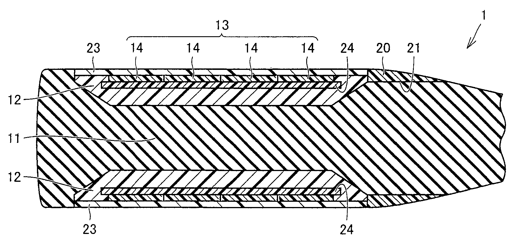
The present invention provides a baseball or softball bat that is both durable and has improved repulsiveness. The bat has an outer shell made of multiple independently deformable portions. This results in reduced energy loss and improved repulsiveness as impact from a ball is transmitted only to the portion with which it comes into contact. Even when the outer shell is an integral pipelike member, it is made up of multiple portions, which allows for increased rigidity and durability while ensuring sufficient repulsiveness. Overall, the invention provides a bat with good durability and improved precision in hitting the ball.

Problems solved by technology

As a result of studying the aforementioned conventional bat, however, the inventor has found the following problem: In other words, while it is necessary to maintain a certain degree of strength in the outer shell member in the bat having the aforementioned structure, the outer shell member does not sufficiently deform or move in batting when the outer shell member of such sufficient strength is employed, and the improvement in the repulsiveness of the bat has been insufficient as a result.
On the other hand, while a countermeasure of reducing rigidity of the outer shell member or employing a material softer than ever as the elastic body is conceivable in order to sufficiently deform the outer shell member or the elastic body in batting in the bat having the structure disclosed in Patent Document 1, such a new problem arises in this case that the durability of the bat lowers to deteriorate the batting feeling.

Method used


Image

  • Baseball or softball bat
  • Baseball or softball bat
  • Baseball or softball bat

Examples


first embodiment

[0069](First Embodiment)

[0070]A first embodiment of the bat according to the present invention is described with reference to FIGS. 1 to 3.

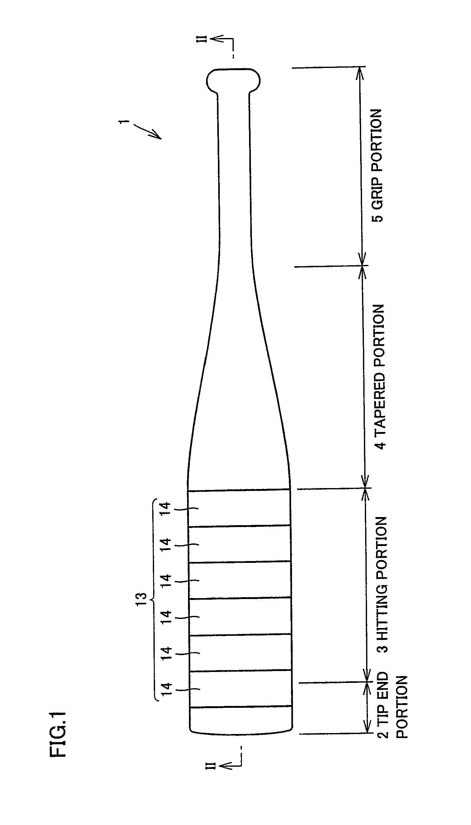
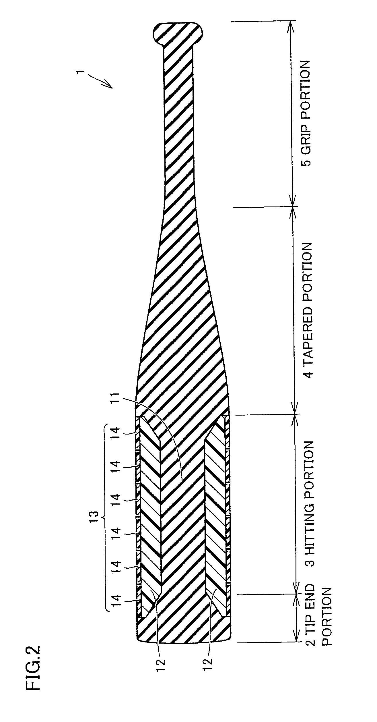
[0071]A bat 1 shown in FIGS. 1 to 3 includes a tip end portion 2, a hitting portion 3 for hitting a ball, a tapered portion 4 whose diameter gradually narrows, and a grip portion 5 for allowing the batter to grip bat 1, from the forward end side. As shown in FIGS. 2 and 3, bat 1 has a three-layer structure in hitting portion 3 of bat 1. In other words, an elastic body 12 is arranged on the outer periphery of a hitting portion core 11 located on a central portion in the radial direction of bat 1 (a central portion in a section perpendicular to the central axis of bat 1) in hitting portion 3. Hitting portion core 11 is provided with a recess 15 for arranging elastic body 12 therein. Elastic body 12 is arranged in recess 15. In recess 15, elastic body 12 is arranged to surround hitting portion core 11. An outer shell member 13 is arranged on the out...

second embodiment

[0077](Second Embodiment)

[0078]A second embodiment of the bat according to the present invention is described with reference to FIGS. 6 to 8.

[0079]While a bat 1 shown in FIGS. 6 to 8 basically has a structure similar to that of the bat shown in FIGS. 1 to 3, the shapes of outer shell member portions 14 constituting an outer shell member 13 are different. In other words, outer shell member portions 14 have oblong shapes extending along the extensional direction of the central axis of bat 1 in bat 1 shown in FIGS. 6 to 8. From a different point of view, outer shell member 13 is in a state divided into plurality of outer shell member portions 14 along the extensional direction of bat 1. Portions of outer shell member portions 14 in contact with an elastic body 12 are entirely or partially connected / fixed to elastic body 12 with a connecting member such as an adhesive. Also according to bat 1 having such a structure, effects similar to those of bat 1 shown in FIGS. 1 to 3 can be attaine...

third embodiment

[0080](Third Embodiment)

[0081]A third embodiment of the bat according to the present invention is described with reference to FIGS. 9 and 10.

[0082]While a bat 1 shown in FIGS. 9 and 10 basically has a structure similar to that of bat 1 shown in FIGS. 1 to 3, the shapes of outer shell member portions 14 constituting an outer shell member 13 are different. In other words, outer shell member 13 is so obliquely (spirally) divided with respect to the extensional direction of bat 1 (the direction along the central axis of bat 1) that outer shell member portions 14 are formed in bat 1 shown in FIGS. 9 and 10. In other words, outer shell member portions 14 have spirally extending outer shapes. Also according to bat 1 having such a shape, effects similar to those of bat 1 shown in FIGS. 1 to 3 can be attained. Further, such spiral outer shell member portions 14 are so employed that outer shell member portions 14 can be utilized as reinforcing members for bat 1 with respect to bending stress ...


PUM


Abstract

A baseball or softball bat improved in repulsiveness while maintaining sufficient durability is obtained. The bat is a baseball or softball bat including a hitting portion, a tapered portion and a grip portion, and the hitting portion offers a hitting portion core as a core, an elastic body and an outer shell member. The elastic body is arranged on the outer periphery of the hitting portion core. The outer shell member is arranged on the outer periphery of the elastic body. The outer shell member includes outer shell member portions which are a plurality of portions elastically deformable independently of each other.

Description

[0001]This nonprovisional application is based on Japanese Patent Application No. 2009-118895 filed on May 15, 2009 and No. 2010-113204 filed on May 17, 2010, with the Japan Patent Office, the entire contents of which are hereby incorporated by reference.BACKGROUND OF THE INVENTION[0002]1. Field of the Invention[0003]The present invention relates to a baseball or softball bat employing an elastic body for a hitting portion, and more specifically, it relates to a baseball or softball bat employing an elastic body for a hitting portion, improved in repulsiveness while maintaining durability.[0004]2. Description of the Background Art[0005]A bat improved in repulsiveness by employing an elastic body for a hitting portion is known in general (refer to Japanese Patent Laying-Open No. 2002-126144 (hereinafter referred to as Patent Document 1), for example). In Patent Document 1, a hitting portion of a bat is constituted of a hitting portion core, an elastic body arranged on the outer perip...

Claims


Application Information

Patent Timeline
Patent Type & Authority Patents(United States)
IPC IPC(8): A63B59/06A63B102/18A63B59/58
CPCA63B59/06A63B59/0092A63B2209/00A63B60/54A63B2102/18A63B59/50A63B59/56A63B2102/182A63B2059/581
Inventor SHINDOME, KAZUHIKOKIDA, TOSHIAKIYAMAGUCHI, YUTAKA
Owner MIZUNO CORPORATION
Learn More