
Three-dimensional projection device

a three-dimensional projection and projector technology, applied in the field of projectors, can solve the problems of large polarization filter, large cost, and large size of conventional 3d projection systems, and achieve the effect of small size, cheaper and more robus

Active Publication Date: 2013-12-10
OCTROLIX
View PDF14 Cites 6 Cited by
  • Summary
  • Abstract
  • Description
  • Claims
  • Application Information

AI Technical Summary

Benefits of technology

This approach results in smaller, cheaper, and more robust 3D projectors with improved optical efficiency, reduced optical cross-talk, and enhanced color reproduction, while maintaining high-quality 3D imaging without the need for complex alignment or external modulators.

Problems solved by technology

Polarization-based 3D projection systems typically provide better color reproduction than color-based 3D projection systems; however, the polarization filters block as much as 50% of the light reaching each eye.
Unfortunately, conventional 3D projection systems are typically large, expensive, and include optical systems that require complex alignment to attain and maintain quality images.

Method used


Image

  • Three-dimensional projection device
  • Three-dimensional projection device
  • Three-dimensional projection device

Examples


Embodiment Construction

[0028]The following terms are defined for use in this Specification, including the appended claims:[0029]Planar lightwave circuit (“PLC”) is defined as an optical circuit that comprises one or more monolithically integrated surface waveguide structures that guide light in two dimensions, wherein the surface waveguides are arranged to provide at least one optical function.[0030]High-contrast waveguide is defined as a surface waveguide characterized by a large difference (≧10%) between the refractive index of its core material and the refractive index of its cladding material.

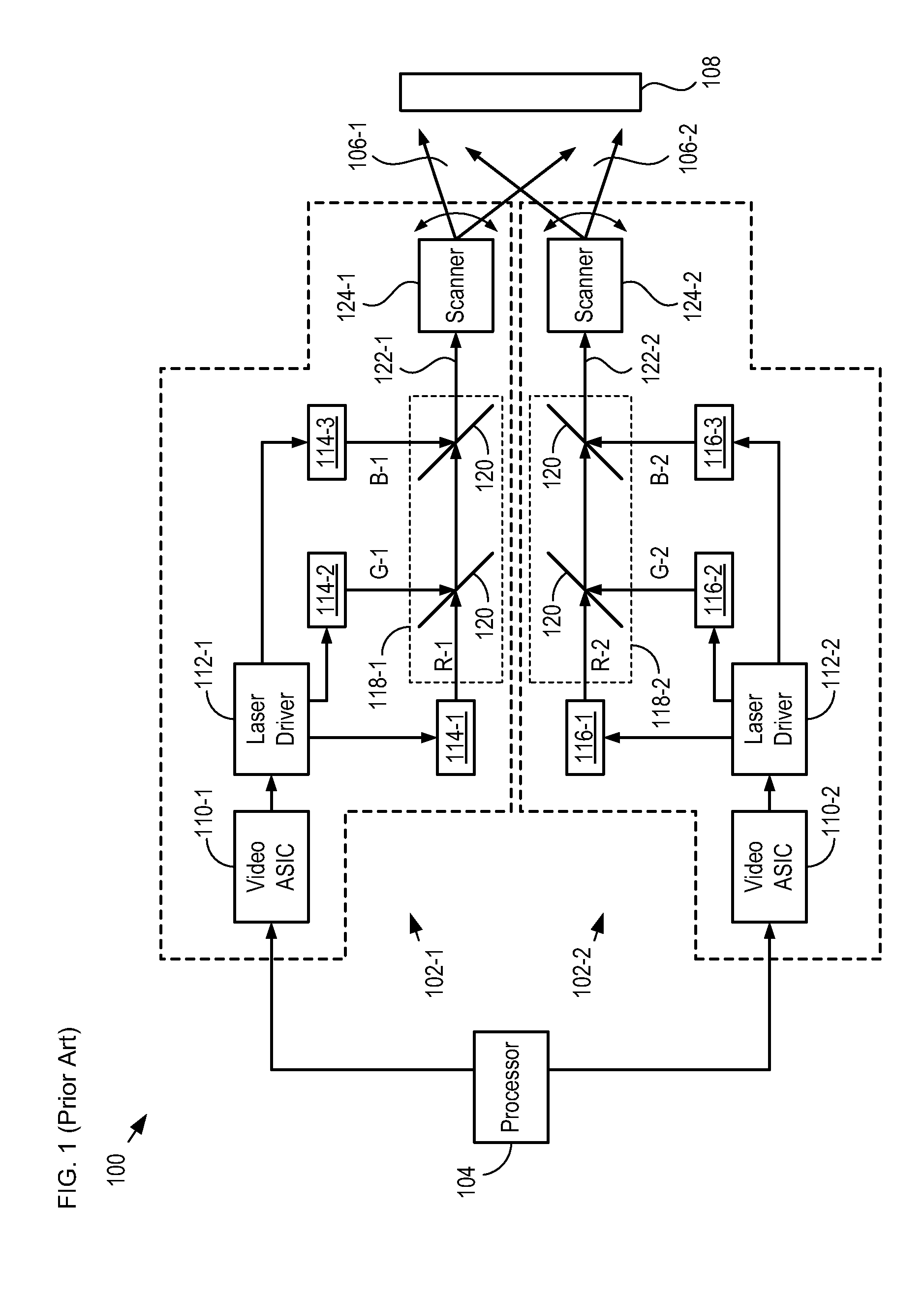
[0031]FIG. 1 depicts a schematic diagram of a portion of a 3D projector in accordance with the prior art. Projector 100 projects two distinct, substantially co-located, two-dimensional images onto display region 108, wherein each of the images has a different polarization state. When viewed using glasses that include different polarization filters in each lens, the images appear to have depth, thereby adding a th...


PUM


Abstract

An image projection system having a laser projector that projects two differently polarized images on a display region is disclosed. The laser projector enables viewing the two differently polarized images as a three-dimensional image. The image projection system includes a planar lightwave circuit-based beam combiner that enables multiple colors of laser light having different polarization modes to be combined in a single output beam that is scanned over the display region at video rates to produce the two polarized images.

Description

CROSS REFERENCE TO RELATED APPLICATIONS[0001]This case is a continuation-in-part of co-pending U.S. patent application Ser. No. 13 / 208,806, entitled “Beam Combiner,” filed Aug. 12, 2011, which claims the benefit of U.S. Provisional Application Ser. No. 61 / 344,553, filed Aug. 19, 2010, U.S. Provisional Application Ser. No. 61 / 376,483, filed Aug. 24, 2010, and U.S. Provisional Application Ser. No. 61 / 477,960, filed Apr. 21, 2011. This case also claims the benefit of U.S. Patent Application 61 / 381,185, filed Sep. 9, 2010. All of these cases are incorporated herein by reference[0002]If there are any contradictions or inconsistencies in language between this application and one or more of the cases that have been incorporated by reference that might affect the interpretation of the claims in this case, the claims in this case should be interpreted to be consistent with the language in this case.FIELD OF THE INVENTION[0003]The present invention relates to projectors in general, and, more ...

Claims


Application Information

Patent Timeline
Patent Type & Authority Patents(United States)
IPC IPC(8): G02B27/26G02B30/25
CPCG03B21/14G03B35/20G03B21/2013G03B21/2033G03B21/2073G03B35/26H04N9/3129H04N13/337H04N13/363
Inventor KLEIN, EDWIN JANDEKKER, RONALD
Owner OCTROLIX
Learn More