Optical lens assembly for image taking
a technology of optical lens and assembly, which is applied in the field of optical lens assembly for image taking, can solve the problems that the change of curvature of the fifth lens element is too large to be conducive to manufacture, and the total length of the aforementioned conventional optical system is usually too long to suit compact electronic device use, etc., and achieves good aberration correction, easy shortening of total length, and flatter edge image surface
- Summary
- Abstract
- Description
- Claims
- Application Information
AI Technical Summary
Benefits of technology
Problems solved by technology
Method used
Image
Examples
first preferred embodiment
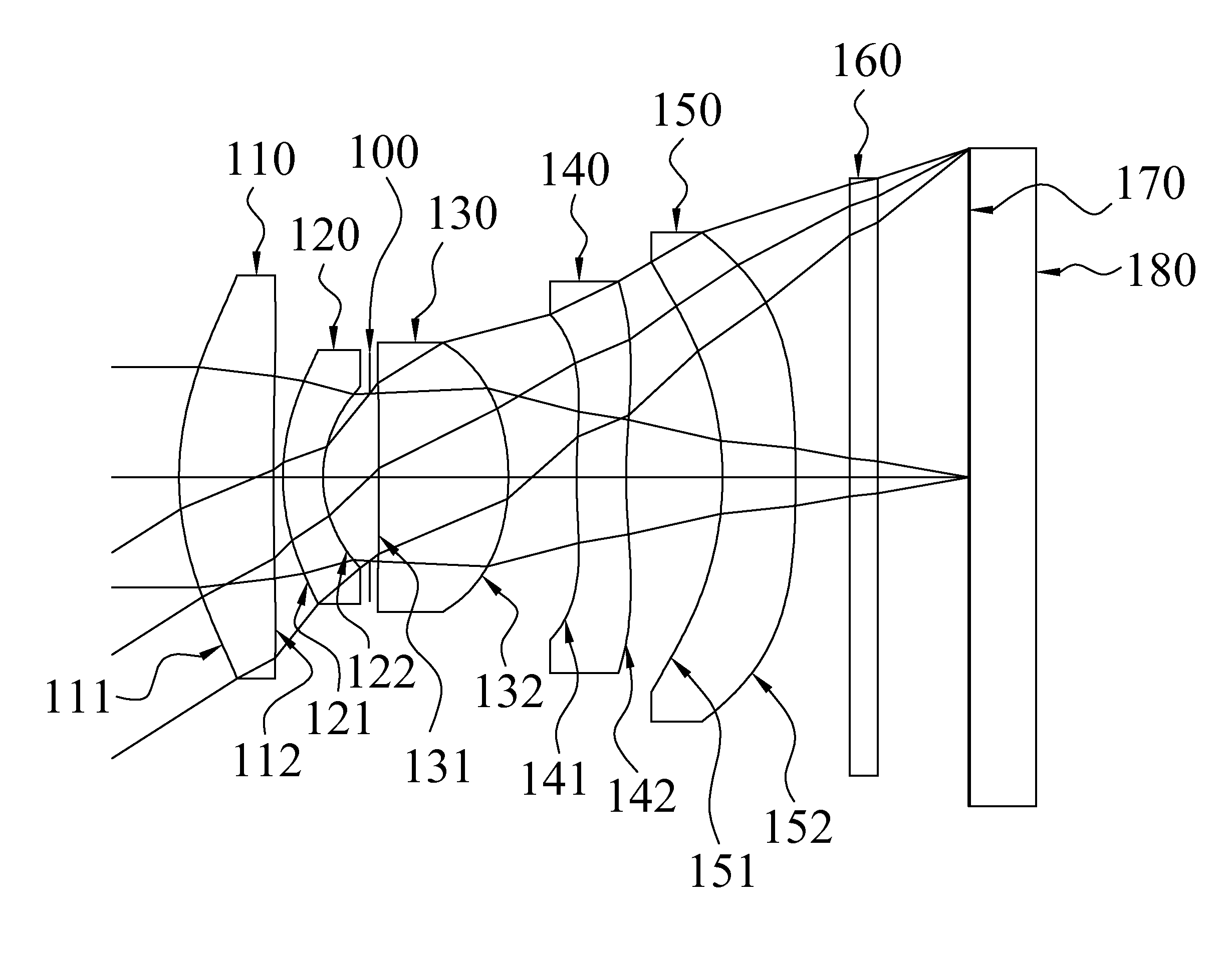
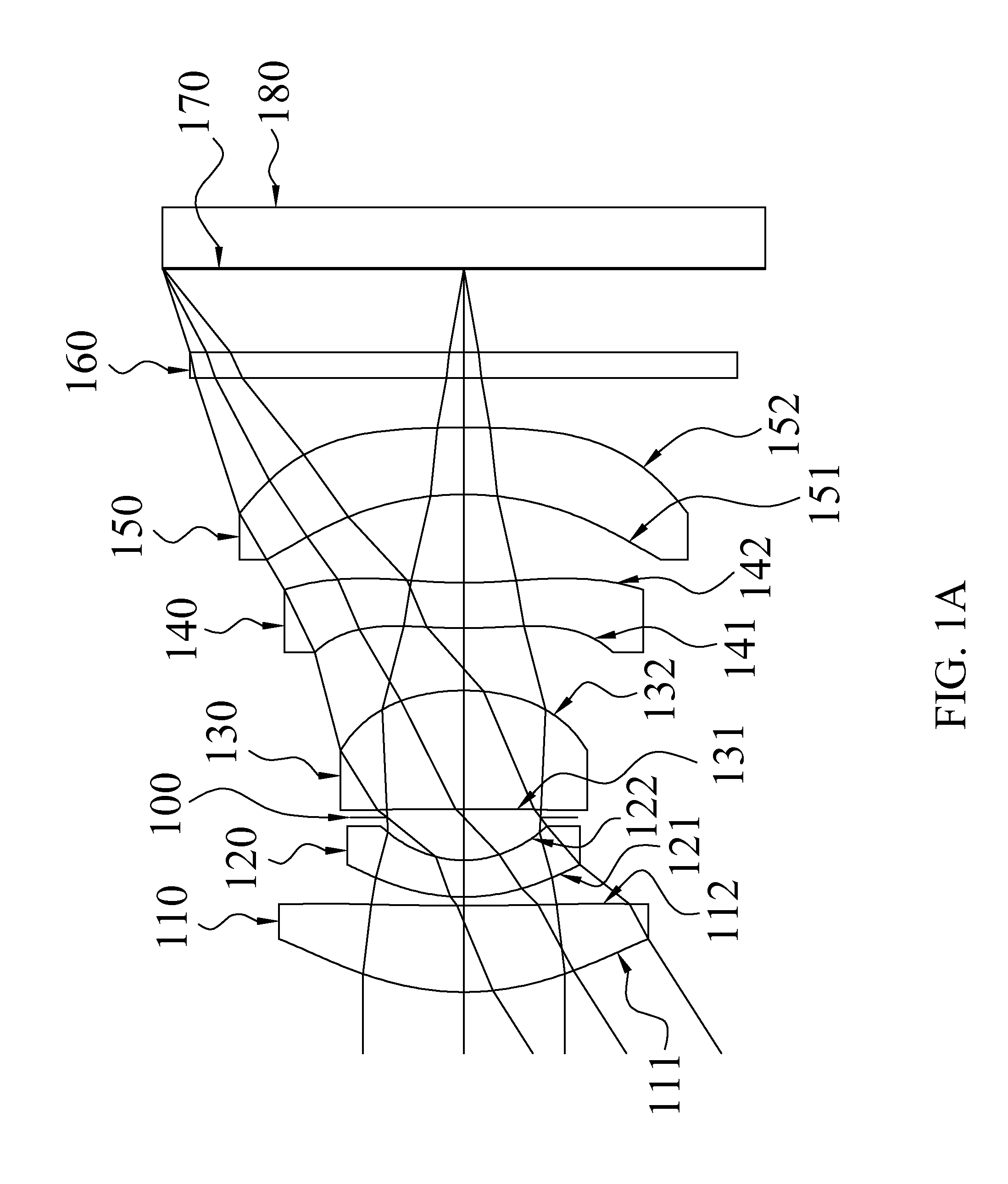
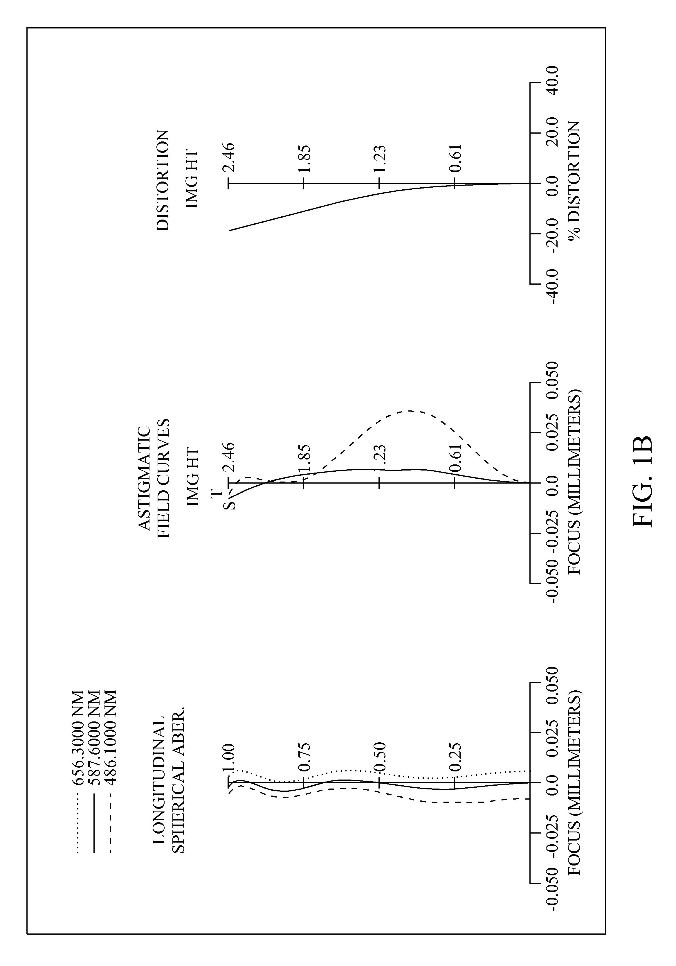
[0049]With reference to FIGS. 1A and 1B for a schematic view of an optical lens assembly for image taking and a series of aberration curves in accordance with the first preferred embodiment of the present invention respectively, the optical lens assembly for image taking primarily comprises five lens elements, a stop and an IR-filter (160). More specifically, the stop can be an aperture stop (100), and the optical lens assembly for image taking; sequentially arranged from an object side to an image side along an optical axis, comprises: a plastic first lens element (110) with positive refractive power, having a convex object-side surface (111) and a concave image-side surface (112), and both object-side surface (111) and image-side surface (112) thereof being aspheric; a plastic second lens element (120) with negative refractive power, having a convex object-side surface (121) and a concave image-side surface (122), and both object-side surface (121) and image-side surface (122) the...
second preferred embodiment
[0056]With reference to FIGS. 2A and 2B for a schematic view of an optical lens assembly for image taking and a series of aberration curves in accordance with the second preferred embodiment of the present invention respectively, the optical lens assembly for image taking comprises five lens elements, a stop and an IR-filter (260). More specifically, the stop can be an aperture stop (200), and the optical lens assembly for image taking, sequentially arranged from an object side to an image side along an optical axis, comprises: a plastic first lens element (210) with positive refractive power, having a convex object-side surface (211) and a concave image-side surface (212), and both object-side surface (211) and image-side surface (212) thereof being aspheric; a plastic second lens element (220) with negative refractive power, having a convex object-side surface (221) and a concave image-side surface (222), and both object-side surface (221) and image-side surface (222) thereof bein...
third preferred embodiment
[0063]With reference to FIGS. 3A and 3B for a schematic view of an optical lens assembly for image taking and a series of aberration curves in accordance with the third preferred embodiment of the present invention respectively, the optical lens assembly for image taking comprises five lens elements, a stop and an IR-filter (360). More specifically, the stop can be an aperture stop (300), and the optical lens assembly for image taking, sequentially arranged from an object side to an image side along an optical axis, comprises: a plastic first lens element (310) with positive refractive power, having a convex object-side surface (311) and a convex image-side surface (312), and both object-side surface (311) and image-side surface (312) thereof being aspheric; a plastic second lens element (320) with negative refractive power, having a convex object-side surface (321) and a concave image-side surface (322), and both object-side surface (321) and image-side surface (322) thereof being ...
PUM
 Abstract
Description
Claims
Application Information
 - R&D
- Intellectual Property
- Life Sciences
- Materials
- Tech Scout
- Unparalleled Data Quality
- Higher Quality Content
- 60% Fewer Hallucinations
Browse by: Latest US Patents, China's latest patents, Technical Efficacy Thesaurus, Application Domain, Technology Topic, Popular Technical Reports.
© 2025 PatSnap. All rights reserved.Legal|Privacy policy|Modern Slavery Act Transparency Statement|Sitemap|About US| Contact US: help@patsnap.com


